Difference between revisions of "Electrical-Mechanical Equipment"
***** (***** | *****) |
***** (***** | *****) |
||
| Line 125: | Line 125: | ||
power - | power - | ||
the pressure of water leaving the runner is reduced to atmospheric or | the pressure of water leaving the runner is reduced to atmospheric or | ||
| − | lower. </span> | + | lower. </span><span /><br> |
| − | == Load | + | == Load Controller: <br> == |
| − | |||
| − | |||
| − | |||
| − | |||
| − | |||
| − | |||
| − | |||
| − | |||
| − | |||
| − | |||
| − | |||
| − | |||
| − | |||
| − | |||
| − | |||
| − | |||
| − | |||
| − | |||
| − | |||
| − | |||
| − | |||
| − | |||
| − | |||
| − | |||
| − | |||
<!--{12766848790530}--><!--{12766848790531}--> <!--{12766848790532}--> | <!--{12766848790530}--><!--{12766848790531}--> <!--{12766848790532}--> | ||
| Line 160: | Line 135: | ||
=== <!--{12766848790533}--><!--{12766848790534}--><!--{12766848790535}--><span lang="DE" style="font-size: 11pt; font-family: Tahoma; color: black;">Function principles </span><span lang="DE" style="font-size: 11pt; font-family: Tahoma; color: black;">[[Image:Mhp-scheme.jpg|right|560x386px|Elements of a Micro Hydro Power Scheme]]</span><br> === | === <!--{12766848790533}--><!--{12766848790534}--><!--{12766848790535}--><span lang="DE" style="font-size: 11pt; font-family: Tahoma; color: black;">Function principles </span><span lang="DE" style="font-size: 11pt; font-family: Tahoma; color: black;">[[Image:Mhp-scheme.jpg|right|560x386px|Elements of a Micro Hydro Power Scheme]]</span><br> === | ||
| − | Load- or Flow- controller ensures that the'''power output not | + | A Load- or Flow- controller ensures that the '''power output does not exceed the power demand''' and power output is stable (e.g. 230V, 50 Hz). |
| − | |||
| − | < | + | <span>Water turbines, like petrol or |
| + | diesel engines, will '''vary in speed as load is applied''' | ||
| + | or relieved. | ||
| + | Although not | ||
| + | such a great problem with machinery which uses direct shaft power, this | ||
| + | speed | ||
| + | variation will seriously '''affect frequency and voltage''' output from a | ||
| + | generator. </span> | ||
| − | < | + | <span>Traditionally, hydraulic or mechanical speed |
| − | + | governors | |
| − | < | + | altered flow as the load varied. Nowadays usually electronic load |
| + | controller (ELC) are used. These prevent speed | ||
| + | variations by | ||
| + | continuously adding or subtracting an artificial load ('''load controller'''). In that in | ||
| + | effect, the | ||
| + | turbine is working permanently under full load and the ELC diverts excess energy into a dump load, mostly a heater.</span> The traditional kind of equalizing power in and output by controlling the flow is usually also automatised ('''flow control'''). Thereby the ELC steers a valve which regulates the amount of water inflowing.<span> | ||
| + | </span> | ||
| − | <br> | + | In case of more power demand than supply the controller cuts off single users (clusters) in order to keep voltage and frequency constant for the others (first and second class connections). Load or flow controller are placed between generator output and the consumer line.<!--{12766848790536}--> <span lang="DE" style="font-size: 11pt; font-family: Tahoma; color: black;"> |
| + | </span><br> | ||
| − | <!--{12766848790537}--><!--{12766848790538}--> <!--{12766848790539}--> | + | <!--{12766848790537}--><!--{12766848790538}--> <!--{12766848790539}--> |
=== <span lang="DE" style="font-size: 11pt; font-family: Tahoma; color: black;">Controller Types</span> === | === <span lang="DE" style="font-size: 11pt; font-family: Tahoma; color: black;">Controller Types</span> === | ||
Revision as of 12:03, 16 June 2010
Ballast or dump load
A ballast load is mostly an electrical resistance heater. It's sized to handle the
full generating capacity of the microhydro turbine. They're placed in air or water. If there is more electricity produced then consumed the charge controller uses this excess energy to generate heat.
Other but not common ballast load may be pumping water or ice production.
Load factor
The load factor is the amount of power used divided by the amount of power that is available if the turbine were to be used continuously. Unlike technologies relying on costly fuel sources, the 'fuel' for hydropower generation is free and therefore the plant becomes more cost effective if run for a high percentage of the time. If the turbine is only used for domestic lighting in the evenings then the plant factor will be very low. If the turbine provides power for rural industry during the day, meets domestic demand during the evening, and maybe pumps water for irrigation in the evening, then the plant factor will be high.
It is very important to ensure a high plant factor if the scheme is to be cost effective and this should be taken into account during the planning stage. Many schemes use a 'dump' load (in conjunction with an electronic load controller - see below), which is effectively a low priority energy demand that can accept surplus energy when an excess is produced e.g. water heating, storage heaters or storage cookers.
Turbine types
[[Image:]]
A turbine converts the energy in falling water into shaft power. There are various types of turbine which can be categorized in one of several ways. The choice of turbine will depend mainly on the pressure head available and the design flow for the proposed hydropower installation. As shown in table 2 below, turbines are broadly divided into three groups; high, medium and low head, and into two categories: impulse and reaction.
Turbine Runner |
Head pressure | ||
|
High |
Medium |
Low | |
|
Impulse |
Pelton Turgo Multi-jet Pelton |
Crossflow Turgo Multi-jet Pelton |
Crossflow |
|
Reaction |
Francis Pump-as-turbine (PAT) |
Propeller Kaplan |
|
The difference between impulse and
reaction can be explained simply by stating that the impulse
turbines
convert the kinetic energy of a jet of water in air into movement by
striking
turbine buckets or blades - there is no pressure reduction as the water
pressure is atmospheric on both sides of the impeller. The blades of a reaction
turbine, on the other hand, are totally immersed in the flow of water,
and the
angular as well as linear momentum of the water is converted into shaft
power -
the pressure of water leaving the runner is reduced to atmospheric or
lower. <span />
Load Controller:
Function principles 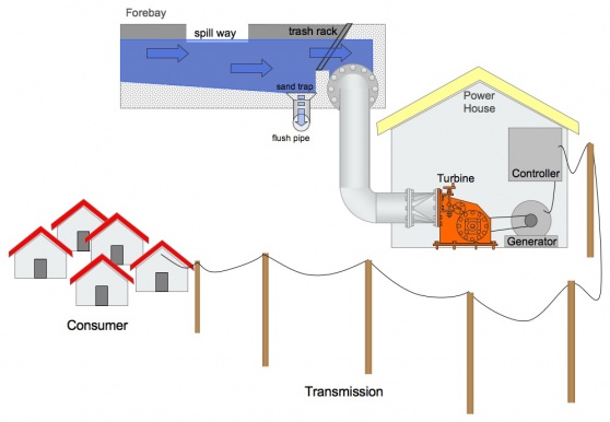

A Load- or Flow- controller ensures that the power output does not exceed the power demand and power output is stable (e.g. 230V, 50 Hz).
Water turbines, like petrol or diesel engines, will vary in speed as load is applied or relieved. Although not such a great problem with machinery which uses direct shaft power, this speed variation will seriously affect frequency and voltage output from a generator.
Traditionally, hydraulic or mechanical speed governors altered flow as the load varied. Nowadays usually electronic load controller (ELC) are used. These prevent speed variations by continuously adding or subtracting an artificial load (load controller). In that in effect, the turbine is working permanently under full load and the ELC diverts excess energy into a dump load, mostly a heater. The traditional kind of equalizing power in and output by controlling the flow is usually also automatised (flow control). Thereby the ELC steers a valve which regulates the amount of water inflowing.
In case of more power demand than supply the controller cuts off single users (clusters) in order to keep voltage and frequency constant for the others (first and second class connections). Load or flow controller are placed between generator output and the consumer line.
Controller Types
Load controller:

Electronic circuit, which keeps output power constant in Frequency- and Voltage- parameters.
Fluctuating energy demand requires a mechanism which either regulates the water input into the turbine (= flow control) or by diverting excess energy from the consumer connection (= ballast load).
Ballast load
usually electrical heaters in water or air. If energy demand is temporarily low the excess energy is converted into heat.
Flow control
regulates the amount of water into the turbine in order to match power output and power demand.
Nowadays flow control is done mostly via electronics (which steer a valve)


