Electrical-Mechanical Equipment
Introduction
disambiguation:
grid connection
island / isolated grids
battery storage / charging stations
Grid connection for mhp's
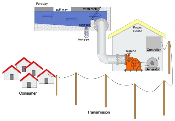
Hydropower usually operates 24 h / day. Most mhp's are connected by a grid to their consumers. If a connection towards the national or main grid is available, electricity can be fed in there. Often micro or pico hydropower units are installed in remote areas. There they feed an isolated grid. In such grid the mhp is usually the only power source. The power produced has to be leveled equal with the power consumed (see controller).
Battery storage is no must like at solar or wind power projects. This is a big advantage as it reduces costs and maintenance significantly. Nevertheless can charging stations extend a mhp's effectiveness by utilising power in times of low demand (late night). So even consumers can be served with are to far from the station to be connected by transmission cable.
Storage basin or dams
Small hydropower plants usually use (part-) river flow as driving force. Storage basins or even dams can buffer water. So demand peaks or (short) periods of water shortage can be bridged. As such infrastructures is costly and sophisticated, it's only used if there is a clear financial revenue; e.g. electricity supply for remote industries.
Off-Grid Batteryless Microhydro-Electric Systems
If the stream has enough potential, one may decide to go with an AC-direct system. This consists of a turbine generator that produces AC output at 120 or 240 volts, which can be sent directly to standard household loads. The system is controlled by diverting energy in excess of load requirements to dump loads, such as water- or air-heating elements. This technique keeps the total load on the generator constant. A limitation of these systems is that the peak or surge loads cannot exceed the output of the generator, which is determined by the stream´s available head and flow. This type of system needs to be large to meet peak electrical loads, so it can often generate enough energy for all household needs, including water and space heating.
The following illustration includes the primary components of any off-grid batteryless microhydro-electric system.
picture ....
Grid-Tied Batteryless Microhydro-Electric Systems
Systems of this type use a turbine and controls to produce electricity that can be fed directly into utility lines. These can use either AC or DC generators. AC systems will use AC generators to sync directly with the grid. An approved interface device is needed to prevent the system from energizing the grid when the grid is out of action and under repair. DC systems will use a specific inverter to convert the output of a DC hydro turbine to grid-synchronous AC. The biggest drawback of batteryless systems is that when the utility is down, your electricity will be out too. When the grid fails, these systems are designed to automatically shut down.
The following illustration includes the primary components of any grid-tied batteryless microhydro-electric system.
[[|]]Microhydro-Electric System Components
Controls
AKA: Charge controller, controller, regulator
[[Image:|Controller]]
The function of a charge controller in a hydro system is equivalent to turning on a load to absorb excess energy. Battery-based microhydro systems require charge controllers to prevent overcharging the batteries. Controllers generally
send
excess energy to a secondary (dump) load, such as an air or water heater. Unlike a solar-electric controller, a microhydro system controller does not disconnect the turbine from the batteries. This could create voltages that are higher than some components can withstand, or cause the turbine to overspeed, which could result in dangerous and damaging overvoltages.
Off-grid, batteryless AC-direct microhydro systems need controls too. A load-control governor monitors the voltage or frequency of the system, and keeps the generator correctly loaded, turning dump-load capacity on and off as the load pattern changes, or mechanically deflects water away from the runner. Grid-tied batteryless AC and DC systems also need controls to protect the system if the utility grid fails.
Dump Load
AKA: diversion load, shunt load
[[Image:|Dump Load 1]][[Image:|Dump Load 2]]
A dump load is an electrical resistance heater that must be sized to handle the
full
generating capacity of the microhydro turbine. Dump loads can be air or water heaters, and are activated by the charge controller whenever the batteries or the grid cannot accept the energy being produced, to prevent damage to the system. Excess energy is "shunted" to the dump load when necessary.
Battery Bank
AKA: storage battery
[[Image:|Battery Bank]]
By using reversible chemical reactions, a battery bank provides a way to store surplus energy when more is being produced than consumed. When demand increases beyond what is generated, the batteries can be called on to release energy to keep your household loads operating.
A microhydro system is typically the most gentle of the RE systems on the batteries, since they do not often remain in a discharged state. The bank can also be smaller than for a wind or PV system. One or two days of storage
is
usually sufficient. Deep-cycle lead-acid batteries are typically used in
these
systems. They are cost effective and do not usually account for a large percentage of the system cost.
Metering
AKA: battery monitor, amp-hour meter, watt-hour meter
[[Image:|Metering]]
System meters measure and display several different aspects of your microhydro-electric system´s performance and status—tracking how full your battery bank is, how much electricity your turbine is producing or has produced, and how much electricity is being used. Operating your system without metering is like running your car without any gauges—although possible to do, it´s always better to know how well the car is operating and how much fuel is in the tank.
[[|]]Main DC Disconnect
AKA: Battery/Inverter disconnect
[[Image:|Main DC Disconnect]]
In battery-based systems, a disconnect between the batteries and inverter is required. This disconnect is typically a large, DC-rated breaker mounted
in a
sheet-metal enclosure. It allows the inverter to be disconnected from the batteries for service, and protects the inverter-to-battery wiring against electrical faults.
Inverter
AKA: DC-to-AC converter
[[Image:|Battery-Based Inverter]]Inverters transform
the DC electricity stored in your battery bank into AC electricity
for powering household appliances. Grid-tied inverters synchronize the system´s output with the utility´s AC electricity, allowing the system to feed hydro-electricity to the utility grid. Battery-based inverters for off-grid or grid-tied systems often include a battery charger, which is capable of charging a battery bank from either the grid or a backup generator if your creek isn´t flowing or your system is down for maintenance.
In rare cases, an inverter and battery bank are used with larger, off-grid AC-direct systems to increase power availability. The inverter uses the AC to charge the batteries, and synchronizes with the hydro-electric AC supply to supplement it when demand is greater than the output of the hydro generator.
[[|]]AC Breaker Panel
AKA: mains panel, breaker box, service entrance
[[Image:|AC Breaker Panel]]
The AC breaker panel, or mains panel, is the point at which all of a home´s electrical wiring meets with the provider of the electricity, whether that´s the grid or a microhydro-electric system. This wall-mounted panel or box is usually installed in a utility room, basement, garage, or on the exterior of a building. It contains a number of labeled circuit breakers that route electricity to the various rooms throughout a house. These breakers allow electricity to be disconnected for servicing, and also protect the building´s wiring against electrical
fires.
Just like the electrical circuits in your home or office, a grid-tied inverter´s electrical output needs to be routed through an AC circuit breaker. This breaker is usually mounted inside the building´s mains panel. It enables
the
inverter to be disconnected from either the grid or from electrical loads if servicing is necessary. The breaker also safeguards the circuit´s electrical wiring.
[[|]]Kilowatt-Hour Meter
AKA: KWH meter, utility meter
[[Image:|Kilowatt-Hour Meter]]
Most homes with grid-tied microhydro-electric systems will have AC electricity both coming from and going to the utility grid. A multichannel KWH meter keeps track of how much grid electricity you´re using and how much your RE system is producing. The utility company often provides intertie-capable meters at
no
cost.
'Turbines'types
[[Image:]]
A turbine converts the energy in falling water into shaft power. There are various types of turbine which
can be
categorised in one of several ways. The choice of turbine will depend mainly on the pressure head available and the design flow for the proposed hydropower installation. As shown in table 2 below, turbines are broadly divided into three groups; high, medium and low head, and into two categories: impulse and reaction.
Turbine Runner |
Head pressure | ||
|
High |
Medium |
Low | |
|
Impulse |
Pelton Turgo Multi-jet Pelton |
Crossflow Turgo Multi-jet Pelton |
Crossflow |
|
Reaction |
Francis Pump-as-turbine (PAT) |
Propeller Kaplan |
|
The difference between impulse and reaction can be explained simply by stating that the impulse turbines convert the kinetic energy of a jet of water in air into movement by striking turbine buckets or blades - there is no pressure reduction as the water pressure is atmospheric on both sides of the impeller. The blades of a reaction turbine, on the other hand, are totally immersed in the flow of water, and the angular as well as linear momentum of the water is converted into shaft power - the pressure of water leaving the runner is reduced to atmospheric or lower.
Load factor
The load factor is the amount of power used divided by the amount of power that is available if the turbine were to be used continuously. Unlike technologies relying on costly fuel sources, the 'fuel' for hydropower generation is free and therefore the plant becomes more cost effective if run for a high percentage of the time. If the turbine is only used for domestic lighting in the evenings then the plant factor will be very low. If the turbine provides power for rural industry during the day, meets domestic demand during the evening, and maybe pumps water for irrigation in the evening, then the plant factor will be high.
It is very important to ensure a high plant factor if the scheme is to be cost effective and this should be taken into account during the planning stage. Many schemes use a 'dump' load (in conjunction with an electronic load controller - see below), which is effectively a low priority energy demand that can accept surplus energy when an excess is produced e.g. water heating, storage heaters or storage cookers.
Load control governors
Water turbines, like petrol or diesel engines, will vary in speed as load is applied or relieved. Although not such a great problem with machinery which uses direct shaft power, this speed variation will seriously affect both frequency and voltage output from a generator. Traditionally, complex hydraulic or mechanical speed governors altered flow as the load varied, but more recently an electronic load controller (ELC) has been developed which has increased the simplicity and reliability of modern micro-hydro sets. The ELC prevents speed variations by continuously adding or subtracting an artificial load, so that in effect, the turbine is working permanently under full load. A further benefit is that the ELC has no moving parts, is very reliable and virtually maintenance free. The advent of electronic load control has allowed the introduction of simple
and
efficient, multi-jet turbines, no longer burdened by expensive hydraulic governors.
Controller:
Function
principles
Load- or Flow- controller ensure that the power output does not exceed the power demand (e.g. 230V, 50 Hz).
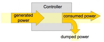
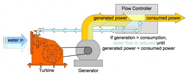
If flow of water in a MHP-station is constant the energy output of a turbine/generator is constant as well. Power demand is usually fluctuating over the time (e.g. day/night). If supply is higher than demand, excess energy must be diverted, dumped. alternatively the water flow can be reduced which results in less power output.
In case of more power demand than supply the controller cuts of the of demand line.
Load controller are placed between generator output and the consumer line.
Controller Types
Load controller:
Electronic circuit, which keeps output power constant in Frequency- and Voltage- parameters.
Fluctuating energy demand requires a mechanism which either regulates the water input into the turbine (= flow control) or by diverting excess energy from the consumer connection (= ballast load).
Ballast load
usually electrical heaters in water or air. If energy demand is temporarily low the excess energy is converted into heat.
Flow control
regulates the amount of water into the turbine in order to match power output and power demand.
Nowadays flow control is done mostly via electronics (which steer a valve)


