Difference between revisions of "Parts of a Biogas Plant"
***** (***** | *****) m (→Digester) |
***** (***** | *****) |
||
| Line 77: | Line 77: | ||
<br/> | <br/> | ||
| + | |||
=== Shapes of Digesters<br/> === | === Shapes of Digesters<br/> === | ||
| − | From the standpoint of fluid dynamics and structural strength, an egg-shaped vessel is about the best possible solution. This type of construction, however, is comparatively expensive, so that its use is usually restricted to large-scale sewage treatment plants. The Chinese [[ | + | From the standpoint of fluid dynamics and structural strength, an egg-shaped vessel is about the best possible solution. This type of construction, however, is comparatively expensive, so that its use is usually restricted to large-scale sewage treatment plants. The Chinese [[Types_of_Biogas_Digesters_and_Plants#Fixed-dome_Plants|fixed-dome]] designs are of similar shape, but less expensive. The hemispherical CAMARTEC design is optimized in structural strength, but does not make optimal use of the excavation required. |
Simplified versions of such digester designs include cylinders with conical covers and bottoms. They are much easier to build and are sometimes available on the market as prefabricated units. Their disadvantage lies in their less favorable surface-volume ratio. The cylinder should have a height equal to its diameter. ''Prone cylinders'' have become quite popular on farms, since they are frequently the more favorable solution for small-scale bio-methanation. ''Cuboid digesters'' are often employed in batch-fed systems used primarily for fermenting solid material, so that fluid dynamics are of little interest. | Simplified versions of such digester designs include cylinders with conical covers and bottoms. They are much easier to build and are sometimes available on the market as prefabricated units. Their disadvantage lies in their less favorable surface-volume ratio. The cylinder should have a height equal to its diameter. ''Prone cylinders'' have become quite popular on farms, since they are frequently the more favorable solution for small-scale bio-methanation. ''Cuboid digesters'' are often employed in batch-fed systems used primarily for fermenting solid material, so that fluid dynamics are of little interest. | ||
| Line 104: | Line 105: | ||
<br/> | <br/> | ||
| + | |||
== Gasholders<br/> == | == Gasholders<br/> == | ||
Revision as of 14:25, 18 March 2014
Overview
The feed material is mixed with water in the influent collecting tank The fermentation slurry flows through the inlet into the digester. The bacteria from the fermentation slurry are intended to produce biogas in the digester. For this purpose, they need time. Time to multiply and to spread throughout the slurry. The digester must be designed in a way that only fully digested slurry can leave it. The bacteria are distributed in the slurry by stirring (with a stick or stirring facilities). The fully digested slurry leaves the digester through the outlet into the slurry storage.The biogas is collected and stored until the time of consumption in the gasholder. The gas pipe carries the biogas to the place where it is consumed by gas appliances. Condensation collecting in the gas pipe is removed by a water trap.
Depending on the available building material and type of plant under construction, different variants of the individual components are possible. The following (optional) components of a biogas plant can also play an important role and are described seperatly: Heating systems, pumps, weak ring.
Influent Collecting Tank
|
Installation of a fixed-dome plant in Thailand: The influent collecting tank is in front of the photo, the digester and the outlet are located behind it.[1] |
Size and Homogenization
Fresh substrate is usually gathered in an influent collecting tank prior to being fed into the digester. Depending on the type of system, the tank should hold one to two days' substrate. An influent collecting tank can also be used to homogenize the various substrates and to set up the required consistency, e.g. by adding water to dilute the mixture of vegetable solids (straw, grass, etc.), or by adding more solids in order to increase the bio-mass. The fibrous material is raked off the surface, if necessary, and any stones or sand settling at the bottom are cleaned out after the slurry is admitted to the digester. The desired degree of homogenization and solids content can be achieved with the aid of an agitator, pump or chopper. A rock or wooden plug can be used to close off the inlet pipe during the mixing process.
Location
A sunny location can help to warm the contents before they are fed into the digester in order to avoid thermal shock due to the cold mixing water. In the case of a biogas plant that is directly connected to the stable, it is advisable to install the mixing pit deep enough to allow installation of a floating gutter leading directly into the pit. Care must also be taken to ensure that the low position of the mixing pit does not result in premature digestion. For reasons of hygiene, toilets should have a direct connection to the inlet pipe.
Inlet and Outlet
The inlet (feed) and outlet (discharge) pipes lead straight into the digester at a steep angle. For liquid substrate, the pipe diameter should be 10-15 cm, while fibrous substrate requires a diameter of 20-30 cm. The inlet and the outlet pipe mostly consist of plastic or concrete.
Position
Both the inlet and the outlet pipe must be freely accessible and straight, so that a rod can be pushed through to eliminate obstructions and agitate the digester contents. The pipes should penetrate the digester wall at a point below the lowest slurry level (i.e. not through the gas storage). The points of penetration should be sealed and reinforced with mortar.
The inlet pipe ends higher in the digester than the outlet pipe in order to promote more uniform flow of the substrate. In a fixed-dome plant, the inlet pipe defines the bottom line of the gas-holder, acting like a security valve to release over-pressure. In a floating-drum plant, the end of the outlet pipe determines the digester's (constant) slurry level.
Inlet and outlet pipe must be placed in connection with brick-laying. It is not advisable to break holes into the spherical shell afterwards, this would weaken the masonry structure.
Toilet Connection at the Inlet
--> Household Toilets can be connected to a Biogas Digester.
Digester
No matter which design is chosen, the digester (fermentation tank) must meet the following requirements:
- Water/gastightness - watertightness in order to prevent seepage and the resultant threat to soil and groundwater quality; gastightness in order to ensure proper containment of the entire biogas yield and to prevent air entering into the digester (which could result in the formation of an explosive mixture).
- Insulation - if and to which extent depends on the required process temperature, the local climate and the financial means; heat loss should be minimized if outside temperatures are low, warming up of the digester should be facilitated when outside temperatures are high.
- Minimum surface area - keeps cost of construction to a minimum and reduces heat losses through the vessel walls. A spherical structure has the best ratio of volume and surface area. For practical construction, a hemispherical construction with a conical floor is close to the optimum.
- Structural stability - sufficient to withstand all static and dynamic loads, durable and resistant to corrosion.
Internal and External Forces
Two relevant forces act on the digester. The external active earth pressure causes compressive forces within the masonry. The internal hydrostatic and gas pressures causes tensile stress in the masonry. Thus, the external pressure applied by the surrounding earth must be greater at all points than the internal forces. Round and spherical shapes are able to accept the highest forces and distribute them uniformly. Edges and corners lead to peak tensile stresses which can result in cracking.
Shapes of Digesters
From the standpoint of fluid dynamics and structural strength, an egg-shaped vessel is about the best possible solution. This type of construction, however, is comparatively expensive, so that its use is usually restricted to large-scale sewage treatment plants. The Chinese fixed-dome designs are of similar shape, but less expensive. The hemispherical CAMARTEC design is optimized in structural strength, but does not make optimal use of the excavation required.
Simplified versions of such digester designs include cylinders with conical covers and bottoms. They are much easier to build and are sometimes available on the market as prefabricated units. Their disadvantage lies in their less favorable surface-volume ratio. The cylinder should have a height equal to its diameter. Prone cylinders have become quite popular on farms, since they are frequently the more favorable solution for small-scale bio-methanation. Cuboid digesters are often employed in batch-fed systems used primarily for fermenting solid material, so that fluid dynamics are of little interest.
|
Construction of the digester neck with steel reinforcement[2] |
Gasholders
Basically, there are different designs of construction for gasholders used in simple biogas plants
Floating-drum Gasholders
Most floating-drum gas-holders are made of 2-4 mm thick sheet steel, with the sides made of thicker material than the top in order to compensate for the higher degree of corrosive attack. Structural stability is provided by L-bar bracing that also serves to break up surface scum when the drum is rotated. A guide frame stabilizes the gas drum and prevents it from tilting and rubbing against the masonry. The two equally suitable and most frequently used types are:
- an internal rod & pipe guide with a fixed (concrete-embedded) cross pole (an advantageous configuration in connection with an internal gas outlet);
- external guide frame supported on three wooden or steel legs.
For either design, substantial force can be necessary to rotate the drum, especially if it is stuck in a heavy layer of floating scum. Any gas-holder with a volume exceeding 5 m3 should be equipped with a double guide (internal and external).
All grades of steel normally used for gas-holders are susceptible to moisture-induced rusting both in- and outside. Consequently, a long service life requires proper surface protection, including:
- thorough de-rusting and de-soiling
- primer coat of minimum 2 layers
- 2 or 3 cover coats of plastic or bituminous paint.
The cover coats should be reapplied annually. A well-kept metal gas-holder can be expected to last between 3 and 5 years in humid, salty air or 8-12 years in a dry climate.
Materials regarded as suitable alternatives to standard grades of steel are galvanized sheet metal, plastics (glass-fiber reinforced plastic (GRP), plastic sheeting) and ferro-cement with a gas-tight lining. The gas-holders of water-jacket plants have a longer average service life, particularly when a film of used oil is poured on the water seal to provide impregnation.
Fixed-dome Gasholders
A fixed-dome gas-holder can be either the upper part of a hemispherical digester (CAMARTEC design) or a conical top of a cylindrical digester (e.g. Chinese fixed-dome plant). In a fixed-dome plant the gas collecting in the upper part of the dome displaces a corresponding volume of digested slurry.
The following aspects must be considered with regard to design and operation:
- An overflow into and out of the compensation tank must be provided to avoid over-filling of the plant.
- The gas outlet must be located about 10 cm higher than the overflow level to avoid plugging up of the gas pipe.
- A gas pressure of 1 m WC or more can develop inside the gas space. Consequently, the plant must be covered sufficiently with soil to provide an adequate counter-pressure.
- Special care must be taken to properly close the man hole, which may require to weigh down the lid with 100 kg or more. The safest method is to secure the lid with clamps.
The following structural measures are recommended to avoid cracks in the gas-holder:
- The foot of the dome (gas-holder) should be stabilized by letting the foundation slab project out enough to allow for an outer ring of mortar.
- A rated break/pivot ring should be provided at a point located between 1/2 and 2/3 of the minimum slurry level. This in order to limit the occurrence or propagation of cracks in the vicinity of the dome foot and to displace forces through its stiffening/articulating effect such that tensile forces are reduced around the gas space. Alternatively, the lowest point of the gas-holder should be reinforced by a steel ring or the whole gas-holder be reinforced with chicken mesh wire.
Normally, masonry, mortar and concrete are not gas-tight, with or without mortar additives. Gas-tightness can only be achieved through good, careful workmanship and special coatings. The main precondition is that masonry and plaster are strong and free of cracks. Cracked and sandy rendering must be removed. In most cases, a plant with cracked masonry must be dismantled, because not even the best seal coating can render cracks permanently gas-tight.
Some tried and proven seal coats and plasters:
- multi-layer bitumen, applied cold (hot application poses the danger of injury by burns and smoke-poisoning; solvents cause dangerous/explosive vapors). Two to four thick coats required;
- bitumen with aluminum foil, thin sheets of overlapping aluminum foil applied to the still-sticky bitumen, followed by the next coat of bitumen;
- plastics, e.g. epoxy resin or acrylic paint; very good but expensive;
- paraffin, diluted with 2-5% kerosene, heated up to 100°C and applied to the preheated masonry, thus providing an effective (deep) seal. Use kerosene/gas torch to heat masonry.
- multi-layer cement plaster with water-proof elements
In any case, a pressure test must be carried out before the plant is put in service.
Plastic Gasholders
Gas-holders made of plastic sheeting serve as integrated gas-holders, as separate balloon/bag-type gas-holders and as integrated gas-transport/storage elements. For plastic (sheet) gas-holders, the structural details are of less immediate interest than the question of which materials can be used.
Separate Gasholders
Differentiation is made between:
- low-pressure, wet and dry gas-holders (10-50 mbar). Basically, these gas-holders are identical to integrated and/or plastic (sheet) gas-holders. Separate gas-holders cost more and are only worthwhile in case of substantial distances (at least 50-100 m) or to allow repair of a leaky fixed-dome plant. This type of separate gas-holder is also used to buffer extreme differences between gas-production and gas-use patterns.
- medium- or high-pressure gas-holders (8-10 bar / 200 bar)
 Biogas plant with seperate gasholder in Nicaragua[3] Biogas plant with seperate gasholder in Nicaragua[3] |
Neither system can be considered for use in small-scale biogas plants. Even for large-scale plants, they cannot be recommended under the conditions in most developing countries. High-pressure gas storage in steel cylinders (as fuel for vehicles) is presently under discussion. While that approach is possible in theory, it would be complicated and, except in special cases, prohibitively expensive. It would also require the establishment of stringent safety regulations.
Gas Pipe, Valves and Accessories
Biogas Piping
At least 60% of all non-functional biogas units are attributable to defect gas piping. Utmost care has to be taken, therefore, for proper installation. For the sake of standardization, it is advisable to select a single size for all pipes, valves and accessories.
The requirements for biogas piping, valves and accessories are essentially the same as for other gas installations. However, biogas is 100% saturated with water vapor and contains hydrogen-sulfide. Consequently, no piping, valves or accessories that contain any amounts of ferrous metals may be used for biogas piping, because they would be destroyed by corrosion within a short time. The gas lines may consist of standard galvanized steel pipes. Also suitable (and inexpensive) is plastic tubing made of rigid PVC or rigid PE. Flexible gas pipes laid in the open must be UV-resistant.
Steel Pipes
Galvanized steel water supply pipes are used most frequently, because the entire piping system (gas pipe, valves and accessories) can be made of universally applicable English/U.S. Customary system components, i.e. with all dimensions in inches. Pipes with nominal dimensions of 1/2" or 3/4" are adequate for small-to-midsize plants of simple design and pipe lengths of less than 30 m. For larger plants, longer gas pipes or low system pressure, a detailed pressure-loss (pipe-sizing) calculation must be performed.
When installing a gas pipe, special attention must be paid to:
- gas-tight, friction-type joints
- line drainage, i.e. with a water trap at the lowest point of the sloping pipe in order to empty water accumulation
- protection against mechanical impact
|
Stirring device for a european biodigester[4] |
Stirring Facilities
Optimum stirring substantially reduces the retention time. If agitation is excessive, the bacteria have "no time to eat". The ideal is gentle but intensive stirring about every four hours. Of similar importance is the breaking up of a scum layer which has lost contact with the main volume of substrate and is, therefore, not further digested. This top layer can form an impermeable barrier for biogas to move up from the digester to the gas holder.
As a rule of thumb it can be stated that stirring facilities are more important in larger plants than in small scale farm plants.
 Stirring facilities in the digester[5] Stirring facilities in the digester[5] |
Types of Stirring Facilities
- The impeller stirrer has given good results especially in sewage treatment plants.
- The horizontal shaft stirs the fermentation channel without mixing up the phases. Both schemes originate from large-scale plant practice.
- For simple household plants, poking with a stick is the simplest and safest stirring method.
Heating Systems
Normally, because of the rather high involved costs, small-scale biogas plants are built without heating systems. But even for small scale plants, it is of advantage for the bio-methanation process to warm up the influent substrate to its proper process temperature before it is fed into the digester. If possible, cold zones in the digester should be avoided (see also substrate temperature).
In the following, a number of different ways to get the required amount of thermal energy into the substrate are described.
In principle, one can differentiate between:
- direct heating in the form of steam or hot water, and
- indirect heating via heat exchanger, whereby the heating medium, usually hot water, imparts heat while not mixing with the substrate.
Direct Heating
Direct heating with steam has the serious disadvantage of requiring an elaborate steam-generating system (including desalination and ion exchange as water pretreatment) and can also cause local overheating. The high cost is only justifiable for large-scale sewage treatment facilities.
The injection of hot water raises the water content of the slurry and should only be practiced if such dilution is necessary.
Indirect Heating
Indirect heating is accomplished with heat exchangers located either inside or outside of the digester, depending on the shape of the vessel, the type of substrate used, and the nature of the operating mode.
- Floor heating systems have not served well in the past, because the accumulation of sediment gradually hampers the transfer of heat.
- In-vessel heat exchangers are a good solution from the standpoint of heat transfer as long as they are able to withstand the mechanical stress caused by the mixer, circulating pump, etc. The larger the heat-exchange surface, the more uniformly heat distribution can be effected which is better for the biological process.
- On-vessel heat exchangers with the heat conductors located in or on the vessel walls are inferior to in-vessel-exchangers as far as heat-transfer efficiency is concerned, since too much heat is lost to the surroundings. On the other hand, practically the entire wall area of the vessel can be used as a heat-transfer surface, and there are no obstructions in the vessel to impede the flow of slurry.
- Ex-vessel heat exchangers offer the advantage of easy access for cleaning and maintenance.
While in Northern countries, often a substantial amount of the produced biogas is consumed to provide process energy, in countries with higher temperatures and longer sunshine hours, solar-heated water can be a cost-effective solution for heating. Exposing the site of the biogas plant to sunshine, e.g. by avoiding tree shade, is the simplest method of heating.
Pumps
Pumps become necessary parts of a biogas unit, when the amounts of substrate require fast movement and when gravity cannot be used for reasons of topography or substrate characteristics. Pumps transport the substrate from the point of delivery through all the stages of fermentation. Therefore, several pumps and types of pumps may be needed. Pumps are usually found in large scale biogas units.
There are two predominant types of pump for fresh substrate: centrifugal pumps and positive-displacement pumps (reciprocating pumps). Centrifugal pumps operate on the principle of a rapidly rotating impeller located in the liquid flow. They provide high delivery rates and are very robust, i.e. the internals are exposed to little mechanical stress. They do, however, require a free-flowing intake arrangement, because they are not self-priming (regenerative).
Practically all centrifugal pump characteristics are geared to water. They show the delivery rates for various heads, the achievable efficiency levels, and the power requirement for the pump motor. Consequently, such data cannot be directly applied to biogas systems, since the overall performance and efficiency level of a pump for re-circulating slurry may suffer a serious drop-off as compared to its standard "water" rating (roughly 5-10%).
Rotary Pump
Rotary pumps are commonplace in liquid-manure pumping. They are eminently suitable for runny substrates.
A rotary pump has an impeller turning inside a fixed body. The impeller accelerates the medium, and the resulting increase in flow velocity is converted into head or pressure at the rotary pump's discharge nozzle. The shape and size of the impeller can
vary, depending on requirements. The cutter-impeller pump is a special kind of rotary pump. The impeller has hardened cutting edges designed to comminute the substrate.
Limitation of a Centrifugal Pump
Sometimes, namely when the substrate is excessively viscous, a centrifugal pump will no longer do the job, because the condition of the substrate surpasses the pump's physical delivery capacity. In such cases, one must turn to a so-called positive-displacement or reciprocating type of pump in the form of a piston pump, gear pump or eccentric spiral pump, all of which operate on the principle of displacing action to provide positive delivery via one or more enclosed chambers.
Positive Displacement Pumps
Positive displacement pumps offer multiple advantages. Even for highly viscous substrate, they provide high delivery and high efficiency at a relatively low rate of power consumption. Their characteristics - once again for water - demonstrate how little the delivery rate depends on the delivery head. Consequently, most of the characteristics show the delivery rate as a function of pump speed.
The main disadvantage as compared to a centrifugal pump is the greater amount of wear and tear on the internal occasioned by the necessity of providing an effective seal between each two adjacent chambers.
The speed of a positive-displacement pump can be varied to control delivery rate. This matches pump control more closely to precision metering of the substrate.The pressure stability of these self-priming pumps is better than that of rotary pumps, which means that delivery rate is much less dependent on head. Positive- displacement pumps are relatively susceptible to interfering substances, so it makes sense to install comminutors and foreign-matter separators to protect the pumps against coarse and fibrous constituents in the substrate[6].
Rotary-displacement pumps and eccentric singlerotor screw pumps are the most commonly used. Eccentric single-rotor screw pumps have a rotor shaped like a corkscrew running inside a stator made of an elastically resilient material. The action of the rotor produces an advancing space in which the substrate is transported.
Rotary displacement pumps have two counter-rotating rotary pistons with between two and six lobes in an oval body. The two pistons counter-rotate and counterroll with low axial and radial clearance, touching neither each other nor the body of the pump. Their geometry is such that in every position a seal is maintained between the suction side and the discharge side of the pump. The medium is drawn in to fill the spaces on the suction side and is transported to the discharge side[6].
Pump Delivery Lines
Pump delivery lines can be made of steel, PVC (rigid) or PE (rigid or flexible), as well as appropriate flexible pressure tubing made of reinforced plastic or rubber. Solid substrate, e.g. dung, can also be handled via conveyor belt, worm conveyor or sliding-bar system, though none of these could be used for liquid manure. When liquid manure is conducted through an open gutter, small weirs or barrages should be installed at intervals of 20-30 m as a means of breaking up the scum layer.
Each such barrier should cause the scum to fall at least 20-30 cm on the downstream side. All changes of direction should be executed at right angles (90°). Depending on the overall length, the cross gutter should be laid some 30-50 cm deeper than the main gutter. Transitions between a rectangular channel and a round pipe must be gradual. An inclination of about 14% yields optimum flow conditions. The channel bottom must be laid level, since any slope in the direction of flow would only cause the liquid manure to run off prematurely. All wall surfaces should be as smooth as possible.
Industrial transport of Substrate
The transport of stackable substrates is a feature of wet digestion plants through to material infeed or to the stage of wetting down to mash with make-up liquid. Most of the work can be done with loaders of conventional design. It is only when automated feeding takes over that scraper-floor feeders, overhead pushers and screw conveyors are used. Scraper-floor feeders and overhead pushers are able to move virtually all stackable substrates horizontally or up slightly inclined planes. They cannot be used for metering, however. They permit very large holding tanks to be used. Screw conveyors can transport stackable substrates in virtually any direction. The only prerequisites are the absence of large stones and comminution of the substrate to the extent that it can be gripped by the worm and fits inside the turns of the worm's conveyor mechanism. Automatic feeder systems for stackable substrates are often combined with the loading equipment to form a single unit in the biogas plant[1].
Weak Ring
The weak/strong ring improves the gas-tightness of fixed-dome plants It was first introduced in Tanzania and showed promising results. The weak ring separates the lower part of the hemispherical digester, (filled with digesting substrate), from the upper part (where the gas is stored). Vertical cracks, moving upwards from the bottom of the digester, are diverted in this ring of lean mortar into horizontal cracks. These cracks remain in the slurry area where they are of no harm to the gas-tightness. The strong ring is a reinforcement of the bottom of the gas-holder, it could also be seen as a foundation of the gas-holder. It is an additional device to prevent cracks from entering the gas-holder. Weak and strong ring have been successfully combined in the CAMARTEC design
| Photo[7]: Construction of the weak/strong ring of a 16 m3, Tanzania |
Materials and Construction
The weak ring consists of mortar of a mixture of sand, lime and cement (15:3:1). The top of the weak ring restores the horizontal level. It is interrupted only by the inlet pipe passing through. The strong ring rests on the weak ring and is the first layer of the upper part of the hemispherical shell. It consists of a row of header bricks with a concrete package at the outside. In case of soft or uncertain ground soil one may place a ring reinforcement bar in the concrete of the strong ring. The brick of the strong ring should be about three times wider than the brickwork of the upper wall. A detailed description of the weak/strong ring construction can be found in Sasse, Kellner, Kimaro (1991).
Pre-digestion pit for storage of substrates
Sizing depends on:
substrate arisings, digester capacity, length of time to be bridged between successive deliveries, land-use specifics and yield of co-substrates, supply contracts for substrates from off-site sources, possible disruptions in operation
Special considerations:
- Avoid the possibility of storage plant freezing, for example by siting storage tanks indoors, heating storage containers or locating the plant for pits below grade level
- Avoid biodegradation processes that reduce gas yield
- Do not permit intermingling of hygienically problematic and hygienically acceptable substrates
- Implement suitable structural measures to minimise odours
- Avoid material emissions to soil and to the surface and underground water system
Designs
Containers for storing solid substrates in widespread use in agriculture, such as mobile silos, upright silos, plastic-tunnel silos and round-bale silos and open or roofed storage areas (e.g. solid-manure deposits) and pits/hoppers
Containers for storing liquid substrates in widespread use in agriculture, such as tanks and predigester pits
Costs
Storage facilities are generally in place; when new builds are needed the price has to be calculated on
a case-to-case basis factoring in the multiplicity of influencing variables indicated above
Digester
In general terms, digesters consist of the digestion tank as such, which is thermally insulated, plus a heating system, mixer systems and discharge systems for sediments and the spent substrate.
Material for the digester
Acid resistance, in extreme cases when gas desulphurization with air oxygen up to a pH of 2 in the gas chamber.
Consistency under the hydrostatic pressure at the bottom depending on the container height to to 1,2 - 1,8 bar
Technical tightness with respect to (mbar 15) of the gas pressure in the headspace of the container.
Traditional in-situ concrete wall (Ortbeton)
Prefabricated concrete
Stanless steel (V4A, 1.4401, X5CrNiMo17-12-2)
Enameled steel panels
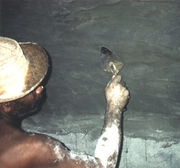 Inside plaster of the gastight section of a fixed dome digester Inside plaster of the gastight section of a fixed dome digesterPhoto: Kellner (TBW) |
In industrialized countries, most of the new digesters are built of gas-tight concrete or steel. Additives are mixed into the concrete to render it gas-tight. If existing concrete vessels are used, their gas-tightness has to be checked. Often, they have not been built from gas-tight concrete or cracks have formed over time which allow the gas to escape.
It is important to check the digester and piping system for gas-tightness prior to putting the biogas unit in service. If leakage is detected only during operation, the digester has to be emptied, cleaned and plastered again. Rectifying a leakage before the initial filling is a lot cheaper.
In developing countries, digesters are usually masonry structures. The plastering has to be watertight up to the lowest slurry level and gas-tight from the lowest gas level upwards (gas-holder). The plaster has to resist moisture and temperatures up to 60°C reliably. The plaster must be resistant to organic acid, ammonia and hydrogen sulfide. The undercoat must be absolutely clean and dry.
Steel
Steel vessels are inherently gas-tight, have good tensile strength, and are relatively easy to construct (by welding). In many cases, a discarded steel vessel of appropriate shape and size can be salvaged for use as a biogas digester. Susceptibility to corrosion both outside (atmospheric humidity) and inside (aggressive media) can be a severe problem. As a rule, some type of anticorrosive coating must be applied and checked at regular intervals. Steel vessels are only cost-effective, if second-hand vessels (e.g. train or truck tankers) can be used.
Concrete
Concrete vessels have gained widespread acceptance in recent years. The requisite gas-tightness necessitates careful construction and the use of gas-tight coatings, linings and/or seal strips in order to prevent gas leakage. Most common are stress cracks at the joints of the top and the sides. The prime advantage of concrete vessels are their practically unlimited useful life and their relatively inexpensive construction. This is especially true for large digesters in industrialized countries.
Cement plaster with special additives
Good results in water- and gas-tightness have been achieved by adding 'water-proofer' to the cement plaster. For gas-tightness, double the amount of water-proofer is required as compared to the amount necessary for water-tightness. The time between the applications of the layers of plaster should not exceed one day, as the plaster becomes water-tight after one day and the new plaster cannot adhere to the old plaster. The following 'recipe' from Tanzania guarantees gas-tightness, provided the masonry structure has no cracks:
- layer: cement-water brushing;
- layer: 1 cm cement : sand plaster 1 : 2.5;
- layer: cement-water brushing;
- layer: cement : lime : sand plaster 1 : 0.25 : 2.5;
- layer: cement-water brushing with water-proofer;
- layer: cement : lime : sand plaster with water proofer and fine, sieved sand 1 : 0.25 : 2.5;
- layer: cement screed (cement-water paste) with water-proofer.
The seven courses of plaster should be applied within 24 hours.
A disadvantage of cement plaster is their inability to bridge small cracks in the masonry structure as, for example, bituminous coats can do.
Bitumen (several layers)
Bitumen coats can be applied easily and remain elastic over long periods of time. Problems arise in the application as the solvents are inflammable (danger of explosion inside the digester) and a health hazard. Bitumen coats cannot be applied on wet surfaces. The drying of masonry structures requires several weeks, unless some heating device (e.g. a charcoal stove) is placed inside the digester for two to three days. Furthermore, the bituminous coat can be damaged by the up-and-down movement of the slurry.
Bitumen coat with aluminum foil
On the first still sticky bitumen coat, aluminum foil is mounted with generous overlaps. A second layer of bitumen is applied on the aluminum foil. Gas-tightness is usually higher compared to the several layers of bitumen without foil.
Water-thinnable dispersion paint
These paints are free from fire- or health hazards. Most of them, however are not gas-tight and not resistant to moisture. Only those dispersion paints should be used which are explicitly recommended for underwater use and which form a gas-tight film.
Single- and dual component synthetic resin paints
Synthetic resin paints form elastic, gas-tight coats which can resist rather high physical load. They are comparably expensive, their use seems only justified if the coating has to resist mechanical stress. This is usually the case with fixed dome plants. Measurements have given evidence that the masonry structure of a fixed dome stretches, though minimally, after filling and under gas pressure.
Paraffin
Paraffin, diluted with new engine oil, is warmed up to 100 -150°C and applied on the plaster which has been heated up with a flame-thrower. The paraffin enters into the plaster and effects a 'deep-sealing'. If paraffin is not available, simple candles can be melted and diluted with engine
Masonry
Masonry is the most frequent construction method for small scale digesters. Only well-burnt clay bricks, high quality, pre-cast concrete blocks or stone blocks should be used in the construction of digesters. Cement-plastered/rendered masonry is a suitable - and inexpensive - approach for building an underground biogas digester, whereby a dome-like shape is recommended. For domes larger than 20 m3 digester volume, steel reinforcement is advisable. Masons who are to build masonry digesters have to undergo specific training and, initially, require close supervision.
|
Construction of the dome for a 30 m3 digester in Cuba[2] |
Plastics
Plastics have been in widespread use in the field of biogas engineering for a long time. Basic differentiation is made between flexible materials (sheeting) and rigid materials (PE, GRP, etc.). Diverse types of plastic sheeting can be used for constructing the entire digesting chamber (balloon gas holders) or as a vessel cover in the form of a gas-tight "bonnet".
Sheeting made of caoutchouc (india rubber), PVC, and PE of various thickness and description have been tried out in numerous systems. The durability of plastic materials exposed to aggressive slurry, mechanical stress and UV radiation, as well as their gas permeability, vary from material to material and on the production processes employed in their manufacture. Glass-fibre reinforced plastic (GRP) digesters have proven quite suitable, as long as the in-service static stresses are accounted for in the manufacturing process. GRP vessels display good gas-tightness and corrosion resistance. They are easy to repair and have a long useful life span. The use of sandwich material (GRP - foam insulation - GRP) minimizes the on-site insulating work and reduces the cost of transportation and erection.
Wood
A further suitable material for use in the construction of biogas systems is wood. It is often used for building liquid-manure hoppers and spreaders. Wooden digesters require a vapor-proof membrane to protect the insulation. Closed vessels of any appreciable size are very hard to render gas-tight without the aid of plastic sheeting. Consequently, such digesters are very rare.
Agitators
Digester Heating
Heat Transport
Engines
CHP
Combined heat and power (CHP), or cogeneration, refers to the simultaneous generation of both heat and electricity. Depending on the circumstances, a distinction can be drawn between power-led and heat-led CHP plants. The heat-led type should normally be
chosen, because of its higher efficiency. In almost all cases this means using small-scale packaged CHP units with internal combustion engines coupled to a generator. The engines run at a constant speed so that the directly coupled generator can provide electrical energy that is compatible with system frequency. Looking into the future, for driving the generator it will also be possible to use gas microturbines, Stirling engines or fuel cells as alternatives to the conventional pilot ignition gas engines and gas spark ignition engines.
Have a look at this presentation on CHP engines.
Flare systems
In case the storage tanks are unable to take more biogas and/or the gas cannot be used on account of maintenance work or extremely poor quality, the excess has to be disposed of in a safe manner. In Germany, the regulations relating to the operating permit vary from state to state, but installation of an alternative to the CHP unit as ultimate sink is required if the gas flow rate is 20 m3/h or higher. This can take the form of a second cogeneration unit (for example two small CHP units instead of one large one). A margin of safety can be established by installing an emergency flare, as a means of ensuring that the gas can be disposed of in an adequate way. In most cases the authorities stipulate that a provision of this nature be made.
High Temperature Flares have to be obligatory not only for CDM projects to destroy surplus biogas which cant be utilised due to technical problems or overproduction. Investment costs about 1% of the total investment. (Mang).
Measurement instruments
Flow-measuring devices (in the pipes)
Ultrasonically (pre pits)
Radar (pre-pits)
Wheel loader scales
Volume flow
Loading systems
Feeding pumps
Pumps are required to bridge differences in height between the levels of slurry-flow through the biogas unit. They can also be required to mix the substrate or to speed up slow flowing substrates. If substrates have a high solids content and do not flow at all, but cannot be diluted, pumps or transport belts are essential.
Pumps are driven by engines, are exposed to wear and tear and can be damaged. They are costly, consume energy and can disrupt the filling process. For these reasons, pumps should be avoided where possible and methods of dilution and use of the natural gradient be utilized instead.
If pumps cannot be avoided, they can be installed in two ways:
- Dry installation: the pump is connected in line with the pipe. The substrate flows freely up to the pump and is accelerated while passing through the pump.
- Wet installation: the pump is installed with an electric engine inside the substrate. The electric engine is sealed in a watertight container. Alternatively, the pump in the substrate is driven by a shaft, the engine is outside the substrate.
Eccentric spiral pump
This pump has a stainless steel rotor, similar to a cork screw, which turns in an elastic casing. Eccentric spiral pumps can suck from a depth of up to 8.5m and can produce a pressure of up to 24 bar. The are, however, more susceptible to obstructive, alien elements than rotary pumps. Of disadvantage is further the danger of fibrous material wrapping round the spiral.
Rotary piston pump
Rotary piston pumps operate on counter-rotating winged pistons in an oval casing. They can pump and suck as well and achieve pressures of up to 10 bar. The potential quantity conveyed ranges from 0.5 to 4 m3/min. The allow for larger alien objects and more fibrous material than eccentric spiral pumps.
| rotary pumps | chopper pumps | eccentric spiral pump | rotary piston pump | |
|---|---|---|---|---|
| solids content | < 8 % | < 8 % | < 15 % | < 15 % |
| energy input | 3 - 15 kW | 3 - 15 kW | 3 - 22 kW | 3 - 20 kW |
| quantity conveyed | 2 - 6 m3/min | 2 - 6 m3/min | 0,3 - 3,5 m3/min | 0,5 - 4 m3/min |
| pressure | 0,8 - 3,5 bar | 0,8 - 3,5 bar | < 25 bar | < 10 bar |
| structure of substrate | medium long fibers | long fibers | short fibers | medium long fibers |
| max. size of obstructive elements | approx. 5 cm | depending on choppers | approx. 4 cm | approx. 6 cm |
| intake | not sucking | not sucking | sucking | sucking |
| suitability | suitable for large quantities; simple and robust built | suitable for long-fiber substrates which need to be chopped up. | Suitable for high pressures, but susceptible to obstructive bodies | higher pressures than rotary pumps, but higher wear and tear |
| price comparison | cheaper than positive displacement pumps | depending on choppers | similar to rotary piston pump | similar to eccentric spiral pump |
Piping
The piping system connects the biogas plant with the biogas appliances. It has to be safe, economic and should allow the required gas-flow for the specific gas appliance. Galvanized steel (G.I.) pipes or Polyvinyl chloride (PVC) pipes are most commonly used for this purpose. Most prominently, the piping system has to be reliably gas-tight during the life-span of the biogas unit. In the past, faulty piping systems were the most frequent reason for gas losses in biogas units.
Polyvinyl chloride (PVC) piping
Polyvinyl chloride (PVC) pipes and fittings have a relatively low price and can be easily installed. They are available in different qualities with adhesive joints or screw couplings (pressure water pipes). PVC pipes are susceptible to UV radiation and can easily be damaged by playing children. Wherever possible, PVC pipes should be placed underground.
Galvanized Steel Piping
Galvanized steel (G.I.) pipes are reliable and durable alternatives to PVC pipes. They can be disconnected and reused if necessary. They resist shocks and other mechanical impacts. However, galvanized steel pipes are costly and the installation is labor intensive, therefore they are only suitable for places where PVC is unavailable or should not be used.
Pipe Diameters
The necessary pipe diameter depends on the required flow-rate of biogas through the pipe and the distance between biogas digester and gas appliances. Long distances and high flow-rates lead to a decrease of the gas pressure. The longer the distance and the higher the flow rate, the higher the pressure drops due to friction. Bends and fittings increase the pressure losses. G.I. pipes show higher pressure losses than PVC pipes. Table 1 gives some values for appropriate pipe diameters. Using these pipe diameters for the specified length and flow rate, the pressure losses will not exceed 5 mbar.
| Galvanized steel pipe | PVC pipe | |||||
|---|---|---|---|---|---|---|
| Length [m]: | 20 | 60 | 100 | 20 | 60 | 100 |
| Flow-rate [m3/h] | ||||||
| 0.1 | 1/2" | 1/2" | 1/2" | 1/2" | 1/2" | 1/2" |
| 0.2 |
1/2" | 1/2" | 1/2" | 1/2" | 1/2" | 1/2" |
| 0.3 | 1/2" | 1/2" | 1/2" | 1/2" | 1/2" | 1/2" |
| 0.4 | 1/2" | 1/2" | 1/2" | 1/2" | 1/2" | 1/2" |
| 0.5 | 1/2" | 1/2" | 3/4" | 1/2" | 1/2" | 1/2" |
| 1.0 | 3/4" | 3/4" | 3/4" | 1/2" | 3/4" | 3/4" |
| 1.5 | 3/4" | 3/4" | 1" | 1/2" | 3/4" | 3/4" |
| 2.0 |
3/4" | 1" | 1" | 3/4" | 3/4" | 1" |
The values in table 1 show that a pipe diameter of 3/4" is suitable for flow rates up to 1.5 m3/h and distances up to 100 m (PVC pipe). Therefore one could select the diameter of 3/4" as single size for the hole piping system of small biogas plants. Another option is to select the diameter of l" for the main gas pipe and 1/2" for all distribution pipes to the gas appliances.
Lay-out of the Piping System
PVC can be used for all underground pipes or pipes that are protected against sun light and out of the reach of children. For all parts of the piping system that are above ground one should install galvanized steel pipes. Therefore it is recommended to use l" G.I. steel pipes for the visible part of the piping system around the biogas digester. For the main pipe one uses l" PVC pipe placed underground. The distribution pipes should be 1/2" G.I. steel pipes or PVC pipes, depending whether they are installed above or under the wall plastering. But even though G.I. pipes are less susceptible to damage, placing them underground should always be the preferred solution.
PVC pipes have to be laid at least 25 cm deep underground. They should be placed in a sand bed and be covered with sand or fine earth. One should carefully back-fill the ditches in order to avoid stones lying directly above the pipe.
When the piping is installed - and before refilling the ditches - it has to be tested for possible gas leakage. This can be done by pumping air into the closed piping system up to a pressure that is 2.5 times the maximum gas pressure of the biogas plant. If pressure loss occurs within few hours, every joint of the piping system has to be checked with soap water. Soap-bubbles indicate any leakage of gas [8].
The valves, fittings and piping must be mediumproof and corrosion-resistant. Valves and fittings such as couplers, shut-off gate valves, flap traps, cleaning ports and pressure gauges must be readily accessible and operable and they must also be installed
in such a way as to be safe from frost damage. The 'Sicherheitsregeln für Biogasanlagen' (Safety Rules for Biogas Systems) issued by the Bundesverband der landwirtschaftlichen Berufsgenossenschaften (German Agricultural Occupational Health and
Safety Agency) contain information about the regulations for piping, valves and fittings and can be of assistance in achieving compliance with the laws and engineering codes with regard to material properties, safety precautions and leak tests for safe operation of the biogas plant [3-18]. One factor that has proved extremely important is the necessity of providing suitable
means of removing condensate from all piping runs, without exception, or of running the pipes with enough fall to ensure that slight settling or sag cannot produce unintended high points along the runs. On account of the low pressures in the system, very small
quantities of condensate can suffice to cause a complete blockage [9].
Water traps
Due to temperature changes, the moisture-saturated biogas will form inevitably condensation water in the piping system. Ideally, the piping system should be laid out in a way that allows a free flow of condensation water back into the digester. If depressions in the piping system can not be avoided, one or several water traps have to be installed at the lowest point of the depressions. Inclination should not be less than 1%.
Often, water traps cannot be avoided. One has to decide then, if an 'automatic' trap or a manually operated trap is more suitable. Automatic traps have the advantage that emptying - which is easily forgotten - is not necessary. But if they dry up or blow empty, they may cause heavy and extended gas losses. In addition, they are not easily understood. Manual traps are simple and easy to understand, but if they are not emptied regularly, the accumulated condensation water will eventually block the piping system. Both kinds of traps have to be installed in a solid chamber, covered by a lid to prevent an eventual filling up by soil [10].
Valves
To the extent possible, ball valves or cock valves suitable for gas installations should be used as shutoff and isolating elements. The most reliable valves are chrome-plated ball valves. Gate valves of the type normally used for water pipes are not suitable. Any water valves exceptionally used must first be checked for gas-tightness. They have to be greased regularly. A U-tube pressure gauge is quick and easy to make and can normally be expected to meet the requirements of a biogas plant.
The main gas valve has to be installed close to the biogas digester. Sealed T-joints should be connected before and after the main valve. With these T-joints it is possible to test the digester and the piping system separately for their gas-tightness. Ball valves as shutoff devices should be installed at all gas appliances. With shutoff valves, cleaning and maintenance work can be carried out without closing the main gas valve.
Gas Analysis Equipment
Sensors
Sensors in the gas space must satisfy explosion protection requirements and should be resistant to corrosion and high levels of moisture.
- Infrared sensors
- Thermal conductivity sensors
The sensors used to measure the temperature should be installed at various heights so that stratification and inadequate mixing can be detected. Care should also be taken that the sensors are not installed in dead zones or too close to the temperature stabilisation equipment. Resistance sensors (e.g. PT 1000 or PT 100) or thermocouples are suitable for measuring the temperature.
- Electrochemical sensors
- Paramagnetic sensors
- Inductive and capacitive sensors
BiogasBox
Documents on the contruction of biogas plants.
Web
http://biogas.ifas.ufl.edu/ad_development/documents/biogasplants.pdf
https://energypedia.info/index.php/Construction_of_a_Biogas_Plant
http://www.haase-energietechnik.de/en/Products_and_Services/24-e_BiogasBrochure_Feb2011_1.pdf
References
- Ringkamp, M.; Tentscher, W.; Schiller, H.: Preliminary results on: statical optimization of family-sized fixed-dome digesters. Tilche, A.; Rozzi, A. (ed.): Poster Papers. Fifth International Symposium on Anaerobic Digestion, Bologna 1988, pp. 321-324
- Sasse, L.; Kellner, Ch.; Kimaro, A.: Improved Biogas Unit for Developing Countries. Deutsche Gesellschaft für Technische Zusammenarbeit (GTZ) GmbH, Vieweg & Sohn Verlagsgesellschaft Braunschweig, 1991
- J.; Sasse, L. (Deutsche Gesellschaft für Technische Zusammenarbeit): Production and utilization of biogas in rural areas of industrialized and developing countries. TZ-Verlagsgesellschaft mbH, Roßdorf, 1986, 278 S.</span>
This section provides detailed information on materials and devices used in the construction of biogas plants:

