Difference between revisions of "Wind Turbine Technology"
***** (***** | *****) (Created page with "== Wind turbine control concepts<br> == === Aerodynamics<br> === === frame|center|Aerodynamics of a wind turbine bladeStall<br> ...") |
***** (***** | *****) |
||
| Line 1: | Line 1: | ||
| − | == Wind turbine control concepts<br> == | + | == Wind turbine control concepts<br> == |
| − | === Aerodynamics<br> === | + | === Aerodynamics<br> === |
| + | === [[Image:Wind turbine blade aerodynamics.jpg|frame|center|Aerodynamics of a wind turbine blade]]Stall<br> === | ||
| + | [[Image:Wind turbine blade aerodynamics - stall control.jpg|frame|center|Wind turbine blade aerodynamics - stall control.jpg]]Stall Control:<br>– Passive Stall:<br>Power of the wind turbine is limited by the aerodynamic characteristics<br>of the turbine.<br>– Active stall:<br>Power of the wind turbine is limited additionally by decreasing the pitch<br>angle (increasing the inflow angle ).<br> | ||
| − | === | + | === Pitch<br> === |
| − | [[Image: | + | [[Image:Wind turbine blade aerodynamics - pitching.jpg|frame|center|Aerodynamics at a wind turbine blade during control through pitching]]Pitch Control:<br>– Power of the wind turbine is limited by increasing the pitch angle<br>(decreasing the inflow angle <math>\alpha</math>)<br> |
| − | == | + | == Wind turbine operation<br> == |
| − | + | === Operation of Fix Speed Wind Turbine (passive stall)<br> === | |
| − | + | • Start up (with open breaker) if wind speed > cut-in wind speed<br>• Close breaker<br>• Operation at constant blade angle over the whole wind speed range<br>• In case of large wind speeds: Power limited by aerodynamic profile.<br> | |
| − | + | <br> | |
| − | + | === Operation of Variable Speed Wind-Turbines<br> === | |
| − | + | Start up (with open breaker) if wind speed > cut-in wi | |
| − | + | [[Image:Typical power curves of wind turbines.jpg|frame|right|Typical power curves of wind turbines.jpg]] | |
| − | + | nd speed<br>• Close breaker<br> | |
| + | |||
| + | |||
| + | |||
| + | |||
| + | |||
| + | • Below rated wind-speed<br>– Maximum power coefficient (Max. Power Tracking)<br> | ||
| + | |||
| + | |||
| + | |||
| + | |||
| + | |||
| + | – Evt: Speed Limitation<br>• Above rated wind-speed:<br>– P=Pr<br>ated (Limited by power electronics converter)<br>– Pitching | ||
• Advantages of variable speed operation:<br>– Lower cut-in wind speeds<br>– Higher efficiency, especially at low wind speeds<br>– Lower power variations (compared to fixed speed turbines)<br>• Disadvantage: More expensive!<br> | • Advantages of variable speed operation:<br>– Lower cut-in wind speeds<br>– Higher efficiency, especially at low wind speeds<br>– Lower power variations (compared to fixed speed turbines)<br>• Disadvantage: More expensive!<br> | ||
| Line 29: | Line 43: | ||
| − | [[Image: | + | |
| + | |||
| + | == Generator concepts<br> == | ||
| + | |||
| + | === Fixed Speed Induction Generator<br> === | ||
| + | |||
| + | [[Image:Fixed_speed_induction_generator.jpg|frame|center]]Only fix speed operation possible (stall control required)<br>• Reactive power compensation required<br>• No reactive power control capability. Additional devices required:<br>– TSCs (Thyristor switched capacitors)<br>– STATCOMs<br>• Risk of dynamic voltage collapse<br>GTZ Expert Workshop 2010: Grid and System Integration of Wind Energy, 22/23.11.2010, Berlin/Germany<br>y g p<br>– > Typically, wind generators based on induction generators are asked to<br>disconnect in case of voltage dips<br> | ||
| + | |||
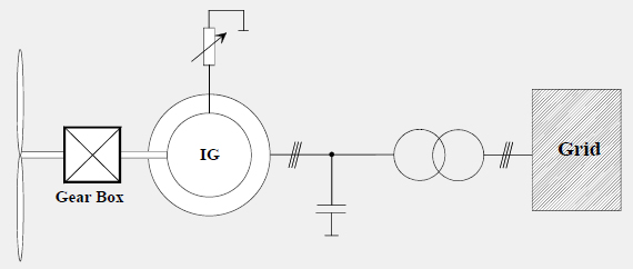
| + | === Induction Generator with Variable Rotor Resistance<br> === | ||
| + | |||
| + | [[Image:Induction_Generator_with_Variable_Rotor_Resistance.jpg|frame|center]]Simple concept for variable speed operation.<br>• Reactive power compensation required.<br>• No reactive power control capability. Additional devices required:<br>– TSCs (Thyristor switched capacitors)<br>– STATCOMs<br>• Limited LVRT capability. Dynamic voltage collapse problems have to<br>GTZ Expert Workshop 2010: Grid and System Integration of Wind Energy, 22/23.11.2010, Berlin/Germany<br>be mitigated by:<br>– Fast increase of rotor resistance during faults<br>– Additional reactive power compensation devices (typically TSCs)<br><br> | ||
Revision as of 15:50, 12 July 2011
Wind turbine control concepts
Aerodynamics
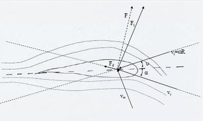
Stall
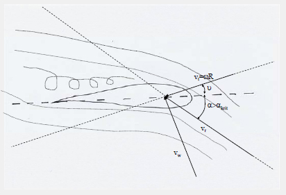
Stall Control:
– Passive Stall:
Power of the wind turbine is limited by the aerodynamic characteristics
of the turbine.
– Active stall:
Power of the wind turbine is limited additionally by decreasing the pitch
angle (increasing the inflow angle ).
Pitch
Pitch Control:
– Power of the wind turbine is limited by increasing the pitch angle
(decreasing the inflow angle )
Wind turbine operation
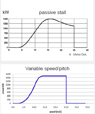
Operation of Fix Speed Wind Turbine (passive stall)
• Start up (with open breaker) if wind speed > cut-in wind speed
• Close breaker
• Operation at constant blade angle over the whole wind speed range
• In case of large wind speeds: Power limited by aerodynamic profile.
Operation of Variable Speed Wind-Turbines
Start up (with open breaker) if wind speed > cut-in wi
nd speed
• Close breaker
• Below rated wind-speed
– Maximum power coefficient (Max. Power Tracking)
– Evt: Speed Limitation
• Above rated wind-speed:
– P=Pr
ated (Limited by power electronics converter)
– Pitching
• Advantages of variable speed operation:
– Lower cut-in wind speeds
– Higher efficiency, especially at low wind speeds
– Lower power variations (compared to fixed speed turbines)
• Disadvantage: More expensive!
Generator concepts
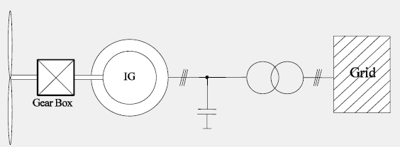
Fixed Speed Induction Generator
Only fix speed operation possible (stall control required)
• Reactive power compensation required
• No reactive power control capability. Additional devices required:
– TSCs (Thyristor switched capacitors)
– STATCOMs
• Risk of dynamic voltage collapse
GTZ Expert Workshop 2010: Grid and System Integration of Wind Energy, 22/23.11.2010, Berlin/Germany
y g p
– > Typically, wind generators based on induction generators are asked to
disconnect in case of voltage dips
Induction Generator with Variable Rotor Resistance
Simple concept for variable speed operation.
• Reactive power compensation required.
• No reactive power control capability. Additional devices required:
– TSCs (Thyristor switched capacitors)
– STATCOMs
• Limited LVRT capability. Dynamic voltage collapse problems have to
GTZ Expert Workshop 2010: Grid and System Integration of Wind Energy, 22/23.11.2010, Berlin/Germany
be mitigated by:
– Fast increase of rotor resistance during faults
– Additional reactive power compensation devices (typically TSCs)

