Difference between revisions of "Biogas Appliances"
***** (***** | *****) m |
***** (***** | *****) |
||
| (13 intermediate revisions by 3 users not shown) | |||
| Line 1: | Line 1: | ||
| − | |||
| − | |||
| − | + | [[Portal:Biogas|►Back to Biogas Portal]] | |
| − | + | ||
| − | | | + | |
| − | < | + | = Overview = |
| + | |||
| + | Biogas is the gaseous product of breaking down organic matter in the absence of oxygen ([[Anaerobic Digestion Technology|Anaerobic Digestion Technology]]). It can be used to meet the energy need for [[Cooking_with_Gas|cooking]] and baking in individual households as well as in small businesses (e.g. restaurants and bakeries) or in communal facilities.<ref name="WISIONS of sustainability: http://www.wisions.net/technologyradar/technology/biogas-stove-oven">WISIONS of sustainability: http://www.wisions.net/technologyradar/technology/biogas-stove-oven</ref> | ||
| + | |||
| + | |||
| + | = Gas Cookers / Stoves<br/> = | ||
| − | < | + | Stoves and ovens for biogas application are similar to conventional appliances that run on commercial fuels such as butane and propane. However, special modifications (particularly in the design of the burners) are required in order to ensure proper combustion and the efficient use of energy.<ref name="WISIONS of sustainability: http://www.wisions.net/technologyradar/technology/biogas-stove-oven">WISIONS of sustainability: http://www.wisions.net/technologyradar/technology/biogas-stove-oven</ref><br/> |
| − | | | + | {| cellspacing="0" cellpadding="10" border="1" style="width: 100%" |
| + | |- | ||
| + | | style="width: 300px;" | | ||
| + | <u>Biogas cookers and stoves must meet various '''basic requirements''':</u><br/> | ||
| − | |||
*simple and easy operation | *simple and easy operation | ||
*versatility, e.g. for pots of various size, for cooking and broiling | *versatility, e.g. for pots of various size, for cooking and broiling | ||
| Line 20: | Line 25: | ||
<br/> | <br/> | ||
| + | |||
| + | | style="width: 270px;" | | ||
| + | '''[[File:Commburner.jpg|150px]]'''<br/> | ||
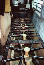
| + | Fig:Institutional burner in a community kitchen<ref name="Krämer (TBW)">Krämer (TBW)</ref><br/> | ||
| + | |||
| + | |} | ||
= Two-flame Burners<br/> = | = Two-flame Burners<br/> = | ||
| − | A cooker is more than just a burner. It must satisfy certain aesthetic and utility requirements, which can vary widely from region to region. Thus, there is no such thing as an all-round biogas burner. Most households prefer two-flame burners. The burners should be set initially and then fixed. Efficiency will then remain at a high practical level. Single-flame burners and lightweight cook-stoves tend to be regarded as stop-gap solutions until more suitable alternatives can be afforded. | + | {| cellspacing="0" cellpadding="10" border="1" style="width: 837px" class="IMGcenter FCK__ShowTableBorders" |
| + | |- | ||
| + | | style="width: 45%" | A cooker is more than just a burner. It must satisfy certain aesthetic and utility requirements, which can vary widely from region to region. Thus, there is no such thing as an all-round biogas burner. Most households prefer two-flame burners. The burners should be set initially and then fixed. Efficiency will then remain at a high practical level. Single-flame burners and lightweight cook-stoves tend to be regarded as stop-gap solutions until more suitable alternatives can be afforded. | ||
| + | | style="width: 0px" | | ||
| + | [[File:2flamestovescheme.gif|376px]] Fig:Lightweight and stable 2-flame biogas burners<ref name="OEKTOP">OEKTOP</ref> | ||
| − | |||
| − | |||
| − | |||
| − | |||
| − | |||
|} | |} | ||
| Line 35: | Line 45: | ||
<u>Biogas cookers require purposeful installation with adequate protection from the wind. Before any cooker is used, the burner must be carefully adjusted, i.e.:</u> | <u>Biogas cookers require purposeful installation with adequate protection from the wind. Before any cooker is used, the burner must be carefully adjusted, i.e.:</u> | ||
| + | |||
*for a compact, bluish flame | *for a compact, bluish flame | ||
*the pot should be cupped by the outer cone of the flame without being touched by the inner cone | *the pot should be cupped by the outer cone of the flame without being touched by the inner cone | ||
| Line 41: | Line 52: | ||
Test measurements should be performed to optimize the burner setting and minimize consumption. | Test measurements should be performed to optimize the burner setting and minimize consumption. | ||
| − | + | == Burner Design / Modification<br/> == | |
| − | |||
| − | = Burner Design / Modification<br/> = | ||
In developing countries, the main prerequisite of biogas utilization is the availability of specially designed biogas burners or modified consumer appliances. The relatively large differences in gas quality from different plants, and even from one and the same plant (gas pressure, temperature, caloric value, etc.) must be given due consideration. | In developing countries, the main prerequisite of biogas utilization is the availability of specially designed biogas burners or modified consumer appliances. The relatively large differences in gas quality from different plants, and even from one and the same plant (gas pressure, temperature, caloric value, etc.) must be given due consideration. | ||
<u>The modification and adaptation of commercial-type burners is an experimental matter. With regard to butane and propane burners, i.e. the most readily available types, the following pointers are offered:</u> | <u>The modification and adaptation of commercial-type burners is an experimental matter. With regard to butane and propane burners, i.e. the most readily available types, the following pointers are offered:</u> | ||
| + | |||
*Butane/propane gas has up to three times the caloric value of biogas and almost twice its flame-propagation rate. | *Butane/propane gas has up to three times the caloric value of biogas and almost twice its flame-propagation rate. | ||
*Conversion to biogas always results in lower performance values. | *Conversion to biogas always results in lower performance values. | ||
| Line 54: | Line 64: | ||
<u>Practical modification measures include:</u> | <u>Practical modification measures include:</u> | ||
| − | + | *expanding the injector cross section by factor 2-4 in order to increase the flow of gas; | |
| − | |||
**modifying the combustion-air supply, particularly if a combustion-air controller is provided; | **modifying the combustion-air supply, particularly if a combustion-air controller is provided; | ||
**increasing the size of the jet openings (avoid if possible). | **increasing the size of the jet openings (avoid if possible). | ||
| Line 65: | Line 74: | ||
<br/> | <br/> | ||
| − | {| | + | {| cellspacing="1" cellpadding="10" border="1" style="width: 100%" class="FCK__ShowTableBorders" |
|- | |- | ||
| − | | [[File:Lotus Burner Kambodia.jpg| | + | | [[File:Lotus Burner Kambodia.jpg|192px|Lotus Burner Kambodia.jpg]] |
| | | | ||
| − | [[File:Standard burner cambidia.png| | + | [[File:Standard burner cambidia.png|162px|Standard burner cambidia.png]] |
|- | |- | ||
| − | | | + | | Fig:Dew designed burner cup "Lotus" by [http://www.snvworld.org/en/countries/cambodia SNVCambodia]<br/> |
| − | | | + | | Fig:"Standard" burner cup - Cambodia |
| − | "Standard" burner cup - Cambodia | ||
| − | |||
|} | |} | ||
| − | + | <br/> | |
| + | The "Lotus"-burner has a better biogas/oxygen mixing capacity than the "standard"-burner. This is justified by the effective distribution of the biogas. The burner is a special production and doesn´t exist in the normal market of Cambodia. | ||
<br/> | <br/> | ||
| − | + | {| cellspacing="1" cellpadding="0" border="1" style="width: 100%" class="FCK__ShowTableBorders" | |
| − | |||
| − | {| | ||
|- | |- | ||
| − | | [[File:Burning biogas without burner bolivia.JPG| | + | | style="text-align: center; width: 384px" | [[File:Burning biogas without burner bolivia.JPG|155px|Burning biogas without burner bolivia.JPG]] |
| − | | [[File:Biogas burner burning bolivia.JPG| | + | | style="text-align: center; width: 372px" | [[File:Biogas burner burning bolivia.JPG|202px|Biogas burner burning bolivia.JPG]]<br/> |
|- | |- | ||
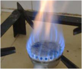
| − | | colspan="2" | Burning biogas without and with burner - Bolivia | + | | colspan="2" style="text-align: center" | Fig: Burning biogas without and with burner - Bolivia |
|} | |} | ||
<br/> | <br/> | ||
| − | {| | + | {| cellspacing="1" cellpadding="1" border="1" style="width: 100%" class="FCK__ShowTableBorders" |
|- | |- | ||
| − | | [[File:Biogas burner bolivia.jpg| | + | | [[File:Biogas burner bolivia.jpg|398px|Biogas burner bolivia.jpg]]<br/> |
| − | | [[File:Biogas burner types bolivia.JPG| | + | | [[File:Biogas burner types bolivia.JPG|320px|Biogas burner types bolivia.JPG]]<br/> |
|- | |- | ||
| Tested biogas burner - Bolivia<br/> | | Tested biogas burner - Bolivia<br/> | ||
| Line 103: | Line 109: | ||
The biogas burner one the left site is the burner with the best carateristics of the tested burners in Bolivia. The burner has a good biogas distribution and heat development with a favorable price at the same time. To optimize the mixture of oxigene and biogas, it is possiple to implent an injector directly in front of the burner (before the gas flows into the burner). This allows, that the biogas is premixed with the oxigene inside the injector tube and the combustion is more complete and effective. | The biogas burner one the left site is the burner with the best carateristics of the tested burners in Bolivia. The burner has a good biogas distribution and heat development with a favorable price at the same time. To optimize the mixture of oxigene and biogas, it is possiple to implent an injector directly in front of the burner (before the gas flows into the burner). This allows, that the biogas is premixed with the oxigene inside the injector tube and the combustion is more complete and effective. | ||
| − | {| | + | {| cellspacing="1" cellpadding="1" border="1" style="width: 100%" class="FCK__ShowTableBorders" |
|- | |- | ||
| − | | [[File:Biogas burner with injector bolivia.JPG| | + | | style="text-align: center" | [[File:Biogas burner with injector bolivia.JPG|center|236px|Biogas burner with injector bolivia.JPG]] |
| − | | | + | | Tested biogas burner with injector. The flame is more "tightly" and the combustion efficiency is better. |
| − | Tested biogas burner with injector. The flame is more "tightly" and the combustion efficiency is better. | ||
| − | |||
|} | |} | ||
| Line 115: | Line 119: | ||
= Biogas Lamps<br/> = | = Biogas Lamps<br/> = | ||
| − | {| | + | {| cellpadding="10" border="1" align="right" style="width: 268px" class="IMGright FCK__ShowTableBorders" |
|- | |- | ||
| − | | [[File:Biogaslampthai.jpg|268px | + | | |
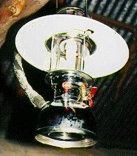
| + | [[File:Biogaslampthai.jpg|268px]]Biogas lamp in Thailand<ref name="Kossmann (gtz/GATE)">Kossmann (gtz/GATE)</ref> | ||
| + | |||
|} | |} | ||
| Line 130: | Line 136: | ||
<br/> | <br/> | ||
| − | {| | + | {| cellpadding="10" border="1" align="left" style="width: 100%" class="IMGleft FCK__ShowTableBorders" |
|- | |- | ||
| − | | | + | | style="width: 212px" | |
| − | + | [[File:Lampscheme s.gif|218px]] | |
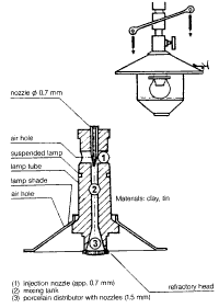
| − | + | Schematic structure of a biogas lamp<ref name="Production and Utilization of Biogas in Rural Areas of Industrialized and Developing Countries, Schriftenreihe der gtz No. 97, p. 186">Production and Utilization of Biogas in Rural Areas of Industrialized and Developing Countries, Schriftenreihe der gtz No. 97, p. 186</ref> | |
| + | | style="width: 505px" | | ||
<u>Optimal Tuning</u><br/> | <u>Optimal Tuning</u><br/> | ||
| Line 143: | Line 150: | ||
<br/> | <br/> | ||
| − | <u | + | <u>Shortcomings of Commercial-type Biogas Lamps</u> |
| + | |||
| + | Practical experience shows that commercial-type gas lamps are not optimally designed for the specific conditions of biogas combustion (fluctuating or low pressure, varying gas composition). | ||
| + | |||
| + | <u>The most frequently observed shortcomings are:</u> | ||
| − | |||
*excessively large nozzle diameters | *excessively large nozzle diameters | ||
*excessively large gas mantles | *excessively large gas mantles | ||
*no possibility of changing the injector | *no possibility of changing the injector | ||
*poor or lacking means of combustion-air control | *poor or lacking means of combustion-air control | ||
| + | |||
| + | |} | ||
Such drawbacks result in unnecessarily high gas consumption and poor lighting. While the expert/extension officer has practically no influence on how a given lamp is designed, he can at least give due consideration to the mentioned aspects when it comes to selecting a particular model. | Such drawbacks result in unnecessarily high gas consumption and poor lighting. While the expert/extension officer has practically no influence on how a given lamp is designed, he can at least give due consideration to the mentioned aspects when it comes to selecting a particular model. | ||
| Line 159: | Line 171: | ||
Biogas lamps are controlled by adjusting the supply of gas and primary air. The aim is to make the gas mantle burn with uniform brightness and a steady, sputtering murmur (sound of burning, flowing biogas). To check the criteria, place the glass on the lamp and wait 2-5 minutes, until the lamp has reached its normal operating temperature. Most lamps operate at a gas pressure of 5-15 cm WC (water column). If the pressure is any lower, the mantle will not glow, and if the pressure is too high (fixed-dome plants) the mantle may tear. | Biogas lamps are controlled by adjusting the supply of gas and primary air. The aim is to make the gas mantle burn with uniform brightness and a steady, sputtering murmur (sound of burning, flowing biogas). To check the criteria, place the glass on the lamp and wait 2-5 minutes, until the lamp has reached its normal operating temperature. Most lamps operate at a gas pressure of 5-15 cm WC (water column). If the pressure is any lower, the mantle will not glow, and if the pressure is too high (fixed-dome plants) the mantle may tear. | ||
| − | {| | + | {| cellpadding="10" border="1" align="left" style="width: 100%" class="IMGleft FCK__ShowTableBorders" |
|- | |- | ||
| − | | [[File:Biogaslampburundi.jpg|279px | + | | style="width: 298px" | |
| − | + | [[File:Biogaslampburundi.jpg|279px]] | |
| + | |||
| + | Biogas lamp in Burundi<ref name="gtz/GATE">gtz/GATE</ref> | ||
| + | |||
| + | | style="width: 419px" | | ||
| + | <u>Adjusting a biogas lamp requires two consecutive steps:</u><br/> | ||
| − | |||
#pre-control of the supply of biogas and primary air without the mantle, initially resulting in an elongated flame with a long inner core | #pre-control of the supply of biogas and primary air without the mantle, initially resulting in an elongated flame with a long inner core | ||
#fine adjustment with the incandescent body in place, resulting in a brightly glowing incandescent body, coupled with slight further adjustment of the air supply (usually more). | #fine adjustment with the incandescent body in place, resulting in a brightly glowing incandescent body, coupled with slight further adjustment of the air supply (usually more). | ||
| − | The adjustment is at its best when the dark portions of the incandescent body have just disappeared. A lux-meter can be used for objective control of the lamp adjustment. | + | The adjustment is at its best when the dark portions of the incandescent body have just disappeared. A lux-meter can be used for objective control of the lamp adjustment.<br/> |
| + | |||
| + | |} | ||
| + | |||
| + | <br/> | ||
| + | |||
| + | <br/> | ||
| + | |||
| + | <br/> | ||
| + | |||
| + | <br/> | ||
<br/> | <br/> | ||
| Line 184: | Line 210: | ||
<br/> | <br/> | ||
| − | {| | + | {| cellpadding="10" border="1" align="right" style="width: 323px" class="IMGright FCK__ShowTableBorders" |
|- | |- | ||
| − | | | + | | |
| + | [[File:Pigletheater.jpg|296px]]Biogas radiant heater for raising piglets in Thailand<ref name="Kossmann (gtz/GATE)">Kossmann (gtz/GATE)</ref> | ||
| + | |||
|} | |} | ||
| Line 227: | Line 255: | ||
= Biogas-fueled Engines<br/> = | = Biogas-fueled Engines<br/> = | ||
| − | + | {| cellspacing="1" cellpadding="5" border="1" style="width: 100%" | |
| − | + | |- | |
| − | <br/> | + | | style="width: 657px" | If the output of a biogas system is to be used for fueling engines, the plant must produce at least 10 m3 biogas per day. For example, to generate 1 kWh electricity with a generator, about 1 m3 biogas is required. Small-scale systems are therefore unsuitable as energy suppliers for engines. |
| + | | style="width: 83px" | | ||
| + | [[File:Cogenunit.jpg|360px]]<br/> | ||
| − | + | Co-generation unit (electricity and heat utilisation)<ref name="Krämer (TBW)">Krämer (TBW)</ref> | |
| − | + | |} | |
<br/> | <br/> | ||
| Line 250: | Line 280: | ||
<u>Less suitable for biogas fueling are</u>: | <u>Less suitable for biogas fueling are</u>: | ||
| + | |||
*loop-scavenging 2-stroke engines in which lubrication is achieved by adding oil to the liquid fuel, and | *loop-scavenging 2-stroke engines in which lubrication is achieved by adding oil to the liquid fuel, and | ||
*large, slow-running (less than 1000 r.p.m) engines that are not built in large series, since they are accordingly expensive and require complicated control equipment. | *large, slow-running (less than 1000 r.p.m) engines that are not built in large series, since they are accordingly expensive and require complicated control equipment. | ||
| Line 272: | Line 303: | ||
<u>To sum up, conversion according to the dual-fuel method is:</u> | <u>To sum up, conversion according to the dual-fuel method is:</u> | ||
| + | |||
*a quick & easy do-it-yourself technique; | *a quick & easy do-it-yourself technique; | ||
*able to accommodate an unsteady supply of biogas; | *able to accommodate an unsteady supply of biogas; | ||
| Line 280: | Line 312: | ||
<u>'''Conversion to Spark Ignition (Otto cycle)''' involves the following permanent modifications at the engine:</u> | <u>'''Conversion to Spark Ignition (Otto cycle)''' involves the following permanent modifications at the engine:</u> | ||
| + | |||
*removing the fuel-injection pump and nozzle | *removing the fuel-injection pump and nozzle | ||
*adding an ignition distributor and an ignition coil with power supply (battery or dynamo) | *adding an ignition distributor and an ignition coil with power supply (battery or dynamo) | ||
| Line 303: | Line 336: | ||
<u>The conversion of spark-ignition engines is evaluated as follows:</u> | <u>The conversion of spark-ignition engines is evaluated as follows:</u> | ||
| + | |||
*Gasoline engines are readily available in the form of vehicle motors, but their useful life amounts to a mere 3000-4000 operating hours. | *Gasoline engines are readily available in the form of vehicle motors, but their useful life amounts to a mere 3000-4000 operating hours. | ||
| Line 309: | Line 343: | ||
<br/> | <br/> | ||
| − | |||
| − | The calorific efficiency of using biogas is 55% in [[ | + | = Efficiency = |
| + | |||
| + | The calorific efficiency of using biogas is 55% in [[Biogas_Appliances#Gas_Cookers_.2F_Stoves|stoves]], 24% in [[Biogas_Appliances#Biogas-fueled_Engines|engines]], but only 3% in [[Biogas_Appliances#Biogas_Lamps|lamps]]. A biogas lamp is only half as efficient as a kerosene lamp. The most efficient way of using biogas is in a heat-power combination where 88% efficiency can be reached. But this is only valid for larger installations and under the condition that the exhaust heat is used profitably. The use of biogas in stoves is the best way of exploiting biogas energy for farm households in developing countries. | ||
<br/> | <br/> | ||
| − | {| | + | {| cellpadding="5" border="1" style="width: 100%" |
|- | |- | ||
| − | ! style="text-align: left;" | appliances | + | ! style="text-align: left; width: 183px; background-color: rgb(204, 204, 204)" | appliances |
| − | | style="width: | + | | style="width: 132px" | gas lamps |
| − | | style="width: | + | | style="width: 117px" | engines |
| − | | style="width: | + | | style="width: 96px" | gas stoves |
| − | | style="width: | + | | style="width: 110px" | power-heat |
|- | |- | ||
| − | ! style="text-align: left;" | efficiency [%] | + | ! style="text-align: left; width: 183px; background-color: rgb(204, 204, 204)" | efficiency [%] |
| − | | style="width: | + | | style="width: 132px" | 3 |
| − | | style="width: | + | | style="width: 117px" | 24 |
| − | | style="width: | + | | style="width: 96px" | 55 |
| − | | style="width: | + | | style="width: 110px" | 88 |
|} | |} | ||
| + | |||
| + | <br/> | ||
<u>For the utilization of biogas, the following consumption rates in liters per hour (l/h) can be assumed:</u> | <u>For the utilization of biogas, the following consumption rates in liters per hour (l/h) can be assumed:</u> | ||
| + | |||
* | * | ||
| − | + | *household burners: 150-450 l/h | |
**industrial burners: 1000-3000 l/h | **industrial burners: 1000-3000 l/h | ||
**refrigerator (100 l) depending on outside temperature: 30-75 l/h | **refrigerator (100 l) depending on outside temperature: 30-75 l/h | ||
| Line 340: | Line 378: | ||
**plastics molding press (15 g, 100 units) with biogas/diesel mixture: 140 l/h | **plastics molding press (15 g, 100 units) with biogas/diesel mixture: 140 l/h | ||
| − | <br/>Biogas can also be used for various other energy requirements in the project region. [[ | + | <br/>Biogas can also be used for various other energy requirements in the project region. [[Biogas_Appliances#Refrigerators|Refrigerators]] and [[Biogas_Appliances#Incubators|chicken heaters]] are the most common applications. In some cases biogas is also used for roasting coffee, baking bread or sterilizing instruments. |
| − | |||
| − | |||
= Further Information<br/> = | = Further Information<br/> = | ||
| − | + | *[[Portal:Biogas|Biogas Portal on energypedia]] | |
| − | + | *[[Cooking_with_Biogas|Cooking with Biogas]] | |
| − | + | *[[Biogas_Stoves|Biogas Stoves]] | |
<br/> | <br/> | ||
| − | |||
| − | + | = References<br/> = | |
| − | < | + | <references /><br/><br/> |
| − | </ | ||
| − | <br/> | ||
| + | [[Category:Heating_and_Cooling]] | ||
| + | [[Category:Heating]] | ||
| + | [[Category:Lighting]] | ||
| + | [[Category:Cookstoves]] | ||
| + | [[Category:Improved_Cooking]] | ||
| + | [[Category:Cooking]] | ||
[[Category:Biogas]] | [[Category:Biogas]] | ||
Latest revision as of 10:10, 19 December 2016
Overview
Biogas is the gaseous product of breaking down organic matter in the absence of oxygen (Anaerobic Digestion Technology). It can be used to meet the energy need for cooking and baking in individual households as well as in small businesses (e.g. restaurants and bakeries) or in communal facilities.[1]
Gas Cookers / Stoves
Stoves and ovens for biogas application are similar to conventional appliances that run on commercial fuels such as butane and propane. However, special modifications (particularly in the design of the burners) are required in order to ensure proper combustion and the efficient use of energy.[1]
|
Biogas cookers and stoves must meet various basic requirements:
|
|
Two-flame Burners
| A cooker is more than just a burner. It must satisfy certain aesthetic and utility requirements, which can vary widely from region to region. Thus, there is no such thing as an all-round biogas burner. Most households prefer two-flame burners. The burners should be set initially and then fixed. Efficiency will then remain at a high practical level. Single-flame burners and lightweight cook-stoves tend to be regarded as stop-gap solutions until more suitable alternatives can be afforded. |
|
Biogas cookers require purposeful installation with adequate protection from the wind. Before any cooker is used, the burner must be carefully adjusted, i.e.:
- for a compact, bluish flame
- the pot should be cupped by the outer cone of the flame without being touched by the inner cone
- the flame should be self-stabilizing, i.e. flameless zones must re-ignite automatically within 2 to 3 seconds
Test measurements should be performed to optimize the burner setting and minimize consumption.
Burner Design / Modification
In developing countries, the main prerequisite of biogas utilization is the availability of specially designed biogas burners or modified consumer appliances. The relatively large differences in gas quality from different plants, and even from one and the same plant (gas pressure, temperature, caloric value, etc.) must be given due consideration.
The modification and adaptation of commercial-type burners is an experimental matter. With regard to butane and propane burners, i.e. the most readily available types, the following pointers are offered:
- Butane/propane gas has up to three times the caloric value of biogas and almost twice its flame-propagation rate.
- Conversion to biogas always results in lower performance values.
Practical modification measures include:
- expanding the injector cross section by factor 2-4 in order to increase the flow of gas;
- modifying the combustion-air supply, particularly if a combustion-air controller is provided;
- increasing the size of the jet openings (avoid if possible).
The aim of all such measures is to obtain a stable, compact, slightly bluish flame.
The different biogas-burners are working with a biogas pressures in a range from 75 mm of water column up to 150 mm of water column. The following shows two examples from Bolivia and Cambodia where different burner designs were tested.
|
|
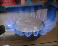
| Fig:Dew designed burner cup "Lotus" by SNVCambodia |
Fig:"Standard" burner cup - Cambodia |
The "Lotus"-burner has a better biogas/oxygen mixing capacity than the "standard"-burner. This is justified by the effective distribution of the biogas. The burner is a special production and doesn´t exist in the normal market of Cambodia.
|
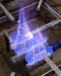 |
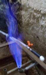
| Fig: Burning biogas without and with burner - Bolivia | |
 |
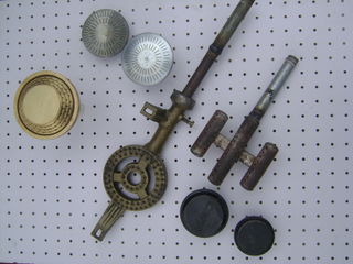 |
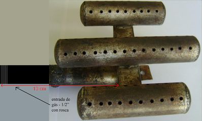
| Tested biogas burner - Bolivia |
Different tested biogas burners |
The biogas burner one the left site is the burner with the best carateristics of the tested burners in Bolivia. The burner has a good biogas distribution and heat development with a favorable price at the same time. To optimize the mixture of oxigene and biogas, it is possiple to implent an injector directly in front of the burner (before the gas flows into the burner). This allows, that the biogas is premixed with the oxigene inside the injector tube and the combustion is more complete and effective.
| Tested biogas burner with injector. The flame is more "tightly" and the combustion efficiency is better. |
Biogas Lamps
|
|
In villages without electricity, lighting is a basic need as well as a status symbol. However, biogas lamps are not very energy-efficient. This means that they also get very hot. The bright light of a biogas lamp is the result of incandescence, i.e. the intense heat-induced luminosity of special metals, so-called "rare earth" like thorium, cerium, lanthanum, etc. at temperatures of 1000-2000°C. If they hang directly below the roof, they cause a fire hazard. The mantles do not last long. It is important that the gas and air in a biogas lamp are thoroughly mixed before they reach the gas mantle, and that the air space around the mantle is adequately warm.
Light Output
The light output (luminous flux) is measured in lumen (lm). At 400-500 lm, the maximum light-flux values that can be achieved with biogas lamps are comparable to those of a normal 25-75 W light bulb. Their luminous efficiency ranges from 1.2 to 2 lm/W. By comparison, the overall efficiency of a light bulb comes to 3-5 lm/W, and that of a fluorescent lamp ranges form 10 to 15 lm/W. One lamp consumes about 120-150 liter biogas per day.
|
Schematic structure of a biogas lamp[5] |
Optimal Tuning The performance of a biogas lamp is dependent on optimal tuning of the incandescent body (gas mantle) and the shape of the flame at the nozzle, i.e. the incandescent body must be surrounded by the inner (=hottest) core of the flame at the minimum gas consumption rate. If the incandescent body is too large, it will show dark spots; if the flame is too large, gas consumption will be too high for the light-flux yield. The lampshade reflects the light downward, and the glass prevents the loss of heat.
Shortcomings of Commercial-type Biogas Lamps Practical experience shows that commercial-type gas lamps are not optimally designed for the specific conditions of biogas combustion (fluctuating or low pressure, varying gas composition). The most frequently observed shortcomings are:
|
Such drawbacks result in unnecessarily high gas consumption and poor lighting. While the expert/extension officer has practically no influence on how a given lamp is designed, he can at least give due consideration to the mentioned aspects when it comes to selecting a particular model.
Adjusting a Biogas Lamp
Biogas lamps are controlled by adjusting the supply of gas and primary air. The aim is to make the gas mantle burn with uniform brightness and a steady, sputtering murmur (sound of burning, flowing biogas). To check the criteria, place the glass on the lamp and wait 2-5 minutes, until the lamp has reached its normal operating temperature. Most lamps operate at a gas pressure of 5-15 cm WC (water column). If the pressure is any lower, the mantle will not glow, and if the pressure is too high (fixed-dome plants) the mantle may tear.
|
Biogas lamp in Burundi[6] |
Adjusting a biogas lamp requires two consecutive steps:
The adjustment is at its best when the dark portions of the incandescent body have just disappeared. A lux-meter can be used for objective control of the lamp adjustment. |
Radiant Heaters
Infrared heaters are used in agriculture for achieving the temperatures required for raising young stock, e.g. piglets and chicken in a limited amount of space. The nursery temperature for piglets begins at 30-35°C for the first week and than gradually drops off to an ambient temperature of 18-23°C in the 4th/5th week. As a rule, temperature control consists of raising or lowering the heater. Good ventilation is important in the stable / nursery in order to avoid excessive concentrations of CO or CO2. Consequently, the animals must be kept under regular supervision, and the temperature must be checked at regular intervals. Heaters for pig or chicken rearing require some 200-300 l/h as a rule of thumb.
Thermal Radiation of Heaters
Radiant heaters develop their infrared thermal radiation via a ceramic body that is heated to 600-800°C (red-hot) by the biogas flame. The heating capacity of the radiant heater is defined by multiplying the gas flow by its net calorific value, since 95% of the biogas' energy content is converted to heat. Small-heater outputs range from 1.5 to 10 kW thermal power.
|
|
Gas Pressure
Commercial-type heaters are designed for operating on butane, propane and natural gas at a supply pressure of between 30 and 80 mbar. Since the primary air supply is factory-set, converting a heater for biogas use normally consists of replacing the injector; experience shows that biogas heaters rarely work satisfactorily because the biogas has a low net calorific value and the gas supply pressure is below 20 mbar. The ceramic panel, therefore, is not adequately heated, i.e. the flame does not reach the entire surface, and the heater is very susceptible to draft.
Safety Pilot and Air Filter
Biogas-fueled radiant heaters should always be equipped with a safety pilot, which turns off the gas supply if the temperatures goes low i.e. the biogas does not burn any longer. An air filter is required for sustained operation in dusty barns.
Incubators
Incubators are supposed to imitate and maintain optimal hatching temperatures for eggs. They are used to increase brooding efficiency.
Warm-water-heated Planar-type Incubators
Indirectly warm-water-heated planar-type incubators in which a burner heats water in a heating element for circulation through the incubating chamber are suitable for operating on biogas. The temperature is controlled by ether-cell-regulated vents.
Refrigerators
Absorption-type refrigerating machines operating on ammonia and water and equipped for automatic thermo-siphon circulation can be fuelled with biogas.
Since biogas is only the refrigerator's external source of heat, just the burner itself has to be modified. Whenever a refrigerator is converted for operating on biogas, care must be taken to ensure that all safety features (safety pilot) function properly. Remote ignition via a piezoelectric element substantially increases the ease of operation.
Gas Demand
For 100 liters refrigeration volume, about 2000 l of biogas per day, depending on outside temperatures, must be assumed. A larger household refrigerator consumes about 3000 l per day.
Biogas-fueled Engines
| If the output of a biogas system is to be used for fueling engines, the plant must produce at least 10 m3 biogas per day. For example, to generate 1 kWh electricity with a generator, about 1 m3 biogas is required. Small-scale systems are therefore unsuitable as energy suppliers for engines. |
Co-generation unit (electricity and heat utilisation)[2] |
Four-stroke Diesel Engines
A diesel engine draws air and compresses it at a ratio of 17:1 under a pressure of approximately 30-40 bar and a temperature of about 700° C. The injected fuel charge ignites itself. Power output is controlled by varying the injected amount of fuel, i.e. the air intake remains constant (so-called mixture control).
Four-stroke Spark-ignition Engines
A spark-ignition engine (gasoline engine) draws a mixture of fuel (gasoline or gas) and the required amount of combustion air. The charge is ignited by a spark plug at a comparably low compression ratio of between 8:1 and 12:1. Power control is effected by varying the mixture intake via a throttle (so-called charge control).
Four-stroke diesel and spark-ignition engines are available in standard versions with power ratings ranging from 1 kW to more than 100 kW.
Less suitable for biogas fueling are:
- loop-scavenging 2-stroke engines in which lubrication is achieved by adding oil to the liquid fuel, and
- large, slow-running (less than 1000 r.p.m) engines that are not built in large series, since they are accordingly expensive and require complicated control equipment.
Biogas engines are generally suitable for powering vehicles like tractors and light-duty trucks (pickups, vans). The fuel is contained in 200-bar steel cylinders (e.g. welding-gas cylinders). The technical, safety and energetic cost of gas compression, storage and filling is substantial enough to hinder large-scale application.
Converting Diesel Engines
Diesel engines are designed for continuous operation (10000 or more operating hours).
Basically, they are well-suited for conversion to biogas utilization according to either of two methods:
In the dual fuel approach the diesel engine remains extensively unmodified, except for the addition of a gas/air mixing chamber on the air-intake manifold (the air filter can be used as a mixing chamber). The injected diesel fuel still ignites itself, while the amount injected is automatically reduced by the speed governor, depending on how much biogas is injected into the mixing chamber. The biogas supply is controlled by hand. The maximum biogas intake must be kept below the point at which the engine begins to stutter. If that happens, the governor gets too much biogas and has turned down the diesel intake to an extent that ignition is no longer steady. Normally, 15-20% diesel is sufficient. As much as 80% of the diesel fuel can thus be replaced by biogas. Any lower share of biogas can also be used, since the governor automatically compensates with more diesel.
As a rule, dual-fuel diesels perform just as well as comparable engines operating on pure diesel. As in normal diesel operation, the speed is controlled by an accelerator lever, and load control is normally effected by hand, i.e. by adjusting the biogas valve (keeping in mind the maximum acceptable biogas intake level). In case of frequent power changes at steady speed, the biogas intake should be somewhat reduced to let the governor decrease the diesel intake without transgressing the minimum diesel intake. Thus, the speed is kept constant, even in case of power fluctuations. Important: No diesel engine should be subjected to air-side control.
While special T-pieces or mixing chambers with a volume of 50 to 100% of the engine cylinder volume can serve as the diesel / biogas mixing chamber, a proper mixing chamber offers the advantage of more thorough mixing.
To sum up, conversion according to the dual-fuel method is:
- a quick & easy do-it-yourself technique;
- able to accommodate an unsteady supply of biogas;
- well-suited for steady operation, since a single manual adjustment will suffice and
- requires a minimum share of diesel to ensure ignition
Conversion to Spark Ignition (Otto cycle) involves the following permanent modifications at the engine:
- removing the fuel-injection pump and nozzle
- adding an ignition distributor and an ignition coil with power supply (battery or dynamo)
- installing spark plugs in place of the injection nozzles
- adding a gas mixing valve or carburetor
- adding a throttle control device
- reducing the compression ratio (ratio of the maximum to the minimum volume of the space enclosed by the piston) to E=11-12
- observing the fact that, as a rule, engines with a pre-combustion or swirl chamber are not suitable for such conversion.
Converting a diesel engine to a biogas-fueled spark-ignition engine is expensive and complicated so that only pre-converted engines of that type should be procured.
Converting Spark-ignition Engines
Converting a spark-ignition engine for biogas fueling requires replacement of the gasoline carburettor with a mixing valve (pressure-controlled venturi type or with throttle). The spark-ignition principle is retained, but should be advanced as necessary to account for slower combustion (approx. 5° -10 ° crankshaft angle) and to avoid overheating of the exhaust valve while precluding loss of energy due to still-combustible exhaust gases. The engine speed should be limited to 3000 rpm for the same reason. As in the case of diesel-engine conversion, a simple mixing chamber should normally suffice for continuous operation at a steady speed. In addition, however, the mixing chamber should be equipped with a hand-operated air-side control valve for use in adjusting the air/fuel ratio (optimal "actual air volume/stoichiometric air volume" = 1.1).
Converting a spark-ignition engine results in a loss of performance amounting to as much as 30%. While partial compensation can be achieved by raising the compression ratio to E=11-12, such a measure also increases the mechanical and thermal load on the engine. Spark-ignition engines that are not explicitly marketed as suitable for running on gas or unleaded gasoline may suffer added wear & tear due to the absence of lead lubrication.
The speed control of converted spark-ignition engines is effected by way of a hand-operated throttle. Automatic speed control for different load conditions requires the addition of an electronic control device for the throttle.
The conversion of spark-ignition engines is evaluated as follows:
- Gasoline engines are readily available in the form of vehicle motors, but their useful life amounts to a mere 3000-4000 operating hours.
The conversion effort essentially consists of adding a (well-turned) gas mixer.
Efficiency
The calorific efficiency of using biogas is 55% in stoves, 24% in engines, but only 3% in lamps. A biogas lamp is only half as efficient as a kerosene lamp. The most efficient way of using biogas is in a heat-power combination where 88% efficiency can be reached. But this is only valid for larger installations and under the condition that the exhaust heat is used profitably. The use of biogas in stoves is the best way of exploiting biogas energy for farm households in developing countries.
| appliances | gas lamps | engines | gas stoves | power-heat |
|---|---|---|---|---|
| efficiency [%] | 3 | 24 | 55 | 88 |
For the utilization of biogas, the following consumption rates in liters per hour (l/h) can be assumed:
- household burners: 150-450 l/h
- industrial burners: 1000-3000 l/h
- refrigerator (100 l) depending on outside temperature: 30-75 l/h
- gas lamp, equiv. to 60 W bulb: 120-150 l/h
- biogas / diesel engine per bhp: 420 l/h
- generation of 1 kWh of electricity with biogas/diesel mixture: 700 l/h
- plastics molding press (15 g, 100 units) with biogas/diesel mixture: 140 l/h
Biogas can also be used for various other energy requirements in the project region. Refrigerators and chicken heaters are the most common applications. In some cases biogas is also used for roasting coffee, baking bread or sterilizing instruments.
Further Information
References
- ↑ 1.0 1.1 WISIONS of sustainability: http://www.wisions.net/technologyradar/technology/biogas-stove-oven
- ↑ 2.0 2.1 Krämer (TBW)
- ↑ OEKTOP
- ↑ 4.0 4.1 Kossmann (gtz/GATE)
- ↑ Production and Utilization of Biogas in Rural Areas of Industrialized and Developing Countries, Schriftenreihe der gtz No. 97, p. 186
- ↑ gtz/GATE

