Difference between revisions of "Hydro Power - Civil Engineering"
***** (***** | *****) m (New page: <!--[if gte mso 10]> <style> →Style Definitions: table.MsoNormalTable {mso-style-name:"Normale Tabelle"; mso-style-parent:""; font-size:10.0pt;"Times New Roman","serif"; mso-fare...) |
***** (***** | *****) |
||
| (47 intermediate revisions by 8 users not shown) | |||
| Line 1: | Line 1: | ||
| − | |||
| − | |||
| − | |||
| − | |||
| − | |||
| − | |||
| − | |||
| − | |||
| − | |||
| − | |||
| − | + | [[Portal:Hydro|► Back to Hydro Portal]] | |
| − | |||
| − | |||
| − | |||
| − | |||
| − | |||
| − | |||
| − | + | == Weir and Intake == | |
| − | |||
| − | |||
| − | |||
| − | + | A (overflow) weir maintains a constant water level in the river at this point. This allows to divert a constant amount of water from the river into canal, '''penstock''' and [[Wind_Turbine_Technology|turbine]]. If there is substantial silt in the water (muddy or sandy grounds) it requires a '''flush gate'''. Such gate can be opened to clear out silt which is usually transported with waters downstream but settles before a weir. | |
| − | |||
| − | ''' | ||
| − | |||
| − | |||
| − | |||
| − | |||
| − | |||
| − | |||
| − | |||
| − | |||
| − | |||
| − | |||
| − | |||
| − | |||
| − | |||
| − | |||
| − | |||
| − | |||
| − | |||
| − | |||
| − | |||
| − | |||
| − | + | Intake is the structure between river an canal. It consists of a gate to open/close the water feed. A rake prevents major debris to enter the system. The intake is located preferably on an outside of a river bend in a way that silt and debris is not “automatically” streamed in. Due to it’s location in/on the river it is to be designed to withstand floods. | |
| − | | | + | [[File:Weir construction.jpg|663px|Weir construction.jpg|alt=Weir construction.jpg]] |
| − | + | <br/> | |
| − | |||
| − | + | == Canal<br/> == | |
| − | + | The canal transports the water towards the point where it drops steeply. To gain much height difference possible it is aligned with as little slope as possible. Canals usually lay on valley slopes. It is to be secured that no waters cross the canal uncontrolled (flushing above or under) from its side.. 1 - ½ meter path between hillside and canal allows its comfortable maintainance and prevents slides blocking the flow. | |
| − | + | <br/> | |
| − | + | == Sandtrap == | |
| − | + | The '''sandtrap''' separates silt and debris from the water before it enters penstock and turbine. It can be placed on the beginning or the end of the canal. The forebay is wider than the canal so the water goes slower. Therefore fine materials such as sand and mud settle at the bottom. A '''flush gate''' or a flush pipe at smaller installations is used to clean the sandtrap during maintainance intervals. A '''spillway''' ensures controlled overflow in case of flooding of canal. | |
| − | |||
| − | turbine | ||
| − | |||
| − | |||
| − | |||
| − | |||
| − | |||
| − | |||
| − | |||
| − | |||
| − | |||
| − | |||
| − | |||
| − | + | [[File:Sand trap forebay.jpg|left|546px|Sand trap forebay.jpg|alt=Sand trap forebay.jpg]] | |
| − | + | == Forebay and Trash Rack == | |
| − | ''' | + | In the '''forebay''' tank the connection towards the '''penstock''' must not be the lowest point. The lowest point is towards a flush pipe. At such sand and mud can be flushed out during maintenance intervals. The '''forebay''' is closed by a '''trash rack'''. It's preventing any debris entering the penstock!<br/>'''Trash rack''' Features: As wide as possible to prevent quick blocking by debris. Grid should be cleanable by a rake from the top. Easy access and comfortable handling make regular cleaning more probable. |
| − | + | [[File:Ererti I forbay , trash rack and flush gate.JPG|thumb|left|180px|Ererti I forbay , trash rack and flush gate.JPG]] | |
| − | + | [[File:Penstock.jpg|right|338px|Penstock.jpg|alt=Penstock.jpg]] | |
| − | |||
| − | |||
| − | < | + | == Pipeline (Penstock)<br/> == |
| − | |||
| − | + | Within the '''penstock''' pipeline the height difference creates pressure on the water. The pressurized water feeds the turbine. On top of the penstock a '''breather pipe''' prevents negative vacuum effects within the pipe during sudden shutting of the '''shutter valve'''. This valve is mounted directly before the turbine. It allows to close the water flow during maintenance or in emergency. This is to be done carefully to prevent a water hammer (strong pressure impulses). A pressure gauge mounted on the pipe before entering the turbine indicates the “'''net-head'''”. It also allows to monitor eventual irregularities within penstock or turbine.<br/><br/>The '''penstock''' is to be rested on '''supports''' in a way that they can slide on top due to heat/cold expansion/shrinking. '''Expansion joints''' are required to avoid changes in length to damage the structure. No forces from penstock must act on neither '''forebay''' nor turbine. Avoid steep angles (>135º) in pipe conduction. It reduces net-head and degrades much quicker than straight pipe (strengthening required on outer bend of an elbow). | |
| − | + | <br/> | |
| − | < | + | == Powerhouse<br/> == |
| − | |||
| − | |||
| − | |||
| − | |||
| − | |||
| − | |||
| − | |||
| − | |||
| − | + | [[File:Powerhouse 3.jpg|right|251px|Powerhouse 3.jpg|alt=Powerhouse 3.jpg]] | |
| − | | | ||
| − | | | ||
| − | |||
| − | + | The turbine, generator, and electrical control have to be protected from: rain, theft and unauthorized access. Moving parts and electrical current can be dangerous for untrained people. The turbine should be nicely accessible, placed min. 1 ½ m from the walls. The location has to be dry even during floods. Rainwater from the hill is to be drained away from the house. | |
| − | |||
| − | |||
| − | + | === Tail Race (water outlet) === | |
| − | + | below the powerhouse is the tail race where the turbine spills its water. Strong forces easily wash out such canal if its not prepared accordingly. The tail race usually feeds back the water to the river. | |
| − | + | <br/> | |
| − | < | + | |
| − | in | + | == Poles (wood pole protection)<br/> == |
| − | + | ||
| − | + | The previously used Boucherie system has not proven successful in the tropics because it was not effective against termites. Experience with this system were made by GTZ in Burundi during the 70th. (one manufacturer of the chemical is/was[http://www.wolman.de/en/about_us/index.php?thisID=67 :]Wolmanit). The necessary 'Boucherie system' pole caps have long been out of industry production. | |
| − | the | + | |
| − | + | ||
| − | </ | + | |
| + | The only effective means (of wood protection) in the tropic is '''Creosote '''because it is also effective against termites. | ||
| + | <div style="text-align: left"><div>The poles can be dipped - but this is not very effectively because only the outer sides of the mast is covered. After a short time the agent runs down the mast. What remains is the bare wood. The only advantage is that thickens the protection is thickend in the earth transition zone.</div><div></div><div>The only effective wood pole protection is the industrial pressure/vacuum process with creosote.</div><div><div><br/></div><div></div><div>Cylindrical steel poles are more durable but more expensive than wood poles.<br/></div><div>Several European manufacturer produce galvanized, octagonal steel poles that can be used.<br/></div><div> | ||
| + | Alternatively and dependend from actual design,<br/>you may keep powerlines short, use local available materials and ensure mechanisms for regular maintenance. | ||
| + | |||
| + | |||
| + | |||
| + | Alternative low cost solutions may be concrete filled bamboo posts. If applicable and resources are available, a locally implemented maintainance system which replaces the posts if necessarymay be a solution too. | ||
| + | </div></div></div> | ||
| + | <br/> | ||
| + | |||
| + | |||
| + | = Further Information = | ||
| + | |||
| + | *[http://www.energyservices.lk/forms/techspec.htm Technical specifications for MHP][http://www.energyservices.lk/forms/techspec.htm - Sri Lanka] | ||
| + | *[http://practicalaction.org/civil-works-guidelines-for-micro-hydropower-in-nepal Civil Works Guidelines for Micro Hydropower in Nepal]<br/> | ||
| + | *[[Portal:Hydro|Hydro portal on energypedia]] | ||
| + | |||
| + | <br/> | ||
| + | |||
| + | [[Category:Hydro]] | ||
| + | |||
| + | = References = | ||
| + | |||
| + | <references /> | ||
[[Category:Hydro]] | [[Category:Hydro]] | ||
Latest revision as of 20:58, 10 November 2015
Weir and Intake
A (overflow) weir maintains a constant water level in the river at this point. This allows to divert a constant amount of water from the river into canal, penstock and turbine. If there is substantial silt in the water (muddy or sandy grounds) it requires a flush gate. Such gate can be opened to clear out silt which is usually transported with waters downstream but settles before a weir.
Intake is the structure between river an canal. It consists of a gate to open/close the water feed. A rake prevents major debris to enter the system. The intake is located preferably on an outside of a river bend in a way that silt and debris is not “automatically” streamed in. Due to it’s location in/on the river it is to be designed to withstand floods.
Canal
The canal transports the water towards the point where it drops steeply. To gain much height difference possible it is aligned with as little slope as possible. Canals usually lay on valley slopes. It is to be secured that no waters cross the canal uncontrolled (flushing above or under) from its side.. 1 - ½ meter path between hillside and canal allows its comfortable maintainance and prevents slides blocking the flow.
Sandtrap
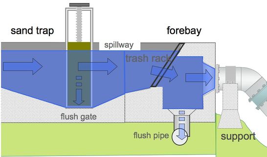
The sandtrap separates silt and debris from the water before it enters penstock and turbine. It can be placed on the beginning or the end of the canal. The forebay is wider than the canal so the water goes slower. Therefore fine materials such as sand and mud settle at the bottom. A flush gate or a flush pipe at smaller installations is used to clean the sandtrap during maintainance intervals. A spillway ensures controlled overflow in case of flooding of canal.
Forebay and Trash Rack
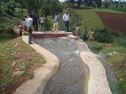
In the forebay tank the connection towards the penstock must not be the lowest point. The lowest point is towards a flush pipe. At such sand and mud can be flushed out during maintenance intervals. The forebay is closed by a trash rack. It's preventing any debris entering the penstock!
Trash rack Features: As wide as possible to prevent quick blocking by debris. Grid should be cleanable by a rake from the top. Easy access and comfortable handling make regular cleaning more probable.
Pipeline (Penstock)
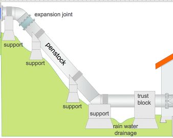
Within the penstock pipeline the height difference creates pressure on the water. The pressurized water feeds the turbine. On top of the penstock a breather pipe prevents negative vacuum effects within the pipe during sudden shutting of the shutter valve. This valve is mounted directly before the turbine. It allows to close the water flow during maintenance or in emergency. This is to be done carefully to prevent a water hammer (strong pressure impulses). A pressure gauge mounted on the pipe before entering the turbine indicates the “net-head”. It also allows to monitor eventual irregularities within penstock or turbine.
The penstock is to be rested on supports in a way that they can slide on top due to heat/cold expansion/shrinking. Expansion joints are required to avoid changes in length to damage the structure. No forces from penstock must act on neither forebay nor turbine. Avoid steep angles (>135º) in pipe conduction. It reduces net-head and degrades much quicker than straight pipe (strengthening required on outer bend of an elbow).
Powerhouse
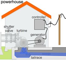
The turbine, generator, and electrical control have to be protected from: rain, theft and unauthorized access. Moving parts and electrical current can be dangerous for untrained people. The turbine should be nicely accessible, placed min. 1 ½ m from the walls. The location has to be dry even during floods. Rainwater from the hill is to be drained away from the house.
Tail Race (water outlet)
below the powerhouse is the tail race where the turbine spills its water. Strong forces easily wash out such canal if its not prepared accordingly. The tail race usually feeds back the water to the river.
Poles (wood pole protection)
The previously used Boucherie system has not proven successful in the tropics because it was not effective against termites. Experience with this system were made by GTZ in Burundi during the 70th. (one manufacturer of the chemical is/was:Wolmanit). The necessary 'Boucherie system' pole caps have long been out of industry production.
The only effective means (of wood protection) in the tropic is Creosote because it is also effective against termites.
Alternatively and dependend from actual design,
you may keep powerlines short, use local available materials and ensure mechanisms for regular maintenance.
Alternative low cost solutions may be concrete filled bamboo posts. If applicable and resources are available, a locally implemented maintainance system which replaces the posts if necessarymay be a solution too.
Further Information
- Technical specifications for MHP- Sri Lanka
- Civil Works Guidelines for Micro Hydropower in Nepal
- Hydro portal on energypedia


