Difference between revisions of "Control Equipment - Hydropower"
***** (***** | *****) m |
***** (***** | *****) m |
||
| Line 38: | Line 38: | ||
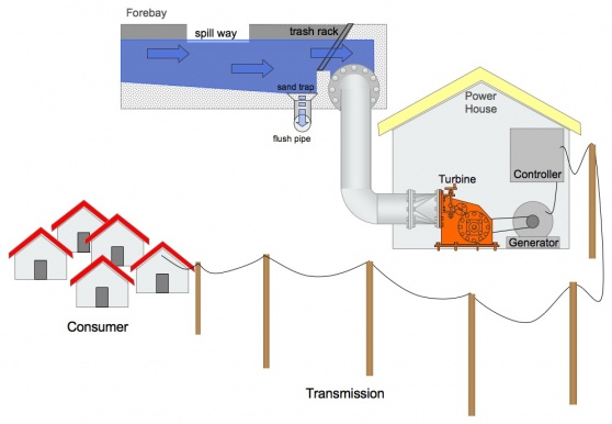
</v:shape><![endif]--><!--[if !vml]--><!--[endif]--><span lang="DE" style="font-size: 11pt; font-family: Tahoma; color: black;">Function:</span><span lang="DE" style="font-size: 11pt; font-family: Tahoma; color: black;">[[Image:Mhp-scheme.jpg|right|560x386px|Elements of a Micro Hydro Power Scheme]]</span> | </v:shape><![endif]--><!--[if !vml]--><!--[endif]--><span lang="DE" style="font-size: 11pt; font-family: Tahoma; color: black;">Function:</span><span lang="DE" style="font-size: 11pt; font-family: Tahoma; color: black;">[[Image:Mhp-scheme.jpg|right|560x386px|Elements of a Micro Hydro Power Scheme]]</span> | ||
| − | + | Load- or Flow- controller ensure that the power output does not exceed the power demand (e.g. 230V, 50 Hz). <br> If flow of water in a MHP-station is constant the energy output of a turbine/generator is constant as well. Power demand is usually fluctuating over the time (e.g. day/night). If supply is higher than demand, excess energy must be diverted, dumped. alternatively the water flow can be reduced which results in less power output. <br> In case of more power demand than supply the controller cuts of the of demand line. <br> Load controller are placed between generator output and the consumer line.<!--EndFragment--> <span lang="DE" style="font-size: 11pt; font-family: Tahoma; color: black;"> | |
| − | |||
| − | |||
| − | |||
| − | |||
| − | ensure that the power output does not exceed the power demand (e.g. 230V, 50 | ||
| − | Hz). < | ||
| − | |||
| − | |||
| − | the energy output of a turbine/generator is constant as well. Power | ||
| − | demand is | ||
| − | usually fluctuating over the time (e.g. day/night). | ||
| − | water flow can be reduced which results in less power output. | ||
| − | |||
| − | |||
| − | the of demand line. | ||
| − | |||
| − | |||
| − | between generator output and the consumer line. | ||
| − | |||
| − | <span lang="DE" style="font-size: 11pt; font-family: Tahoma; color: black;"> | ||
</span> | </span> | ||
| Line 74: | Line 54: | ||
<o:shapelayout v:ext="edit"> | <o:shapelayout v:ext="edit"> | ||
<o:idmap v:ext="edit" data="1"/> | <o:idmap v:ext="edit" data="1"/> | ||
| − | </o:shapelayout></xml><![endif]--> <!--StartFragment--> | + | </o:shapelayout></xml><![endif]--> <!--StartFragment--> |
=== <span lang="DE" style="font-size: 11pt; font-family: Tahoma; color: black;">Control Elements</span> === | === <span lang="DE" style="font-size: 11pt; font-family: Tahoma; color: black;">Control Elements</span> === | ||
Revision as of 08:23, 16 June 2010
Overview:
Function:
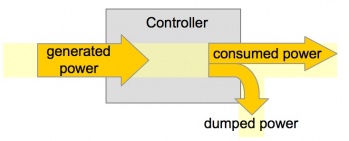
Load- or Flow- controller ensure that the power output does not exceed the power demand (e.g. 230V, 50 Hz).
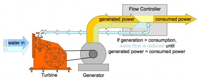
If flow of water in a MHP-station is constant the energy output of a turbine/generator is constant as well. Power demand is usually fluctuating over the time (e.g. day/night). If supply is higher than demand, excess energy must be diverted, dumped. alternatively the water flow can be reduced which results in less power output.
In case of more power demand than supply the controller cuts of the of demand line.
Load controller are placed between generator output and the consumer line.
Control Elements
Load controller:
Electronic circuit, which keeps output power constant in Frequency- and Voltage- parameters.
Fluctuating energy demand requires a mechanism which either regulates the water input into the turbine (= flow control) or by diverting excess energy from the consumer connection (= ballast load).
Ballast load
usually electrical heaters in water or air. If energy demand is temporarily low the excess energy is converted into heat.
Flow control
regulates the amount of water into the turbine in order to match power output and power demand.
Nowadays flow control is done mostly via electronics (which steer a valve)


