Click here to register!
Difference between revisions of "Types of Biogas Digesters and Plants"
***** (***** | *****) m |
***** (***** | *****) m |
||
| Line 6: | Line 6: | ||
*'''Fixed-dome plants''' | *'''Fixed-dome plants''' | ||
*'''Floating-drum plants''' | *'''Floating-drum plants''' | ||
| − | *'''Low-Cost Polyethylene Tube Digester'''<br> | + | *'''Low-Cost Polyethylene Tube Digester'''<br> |
*'''Balloon plants''' | *'''Balloon plants''' | ||
*'''Horizontal plants''' | *'''Horizontal plants''' | ||
| Line 13: | Line 13: | ||
*[[ARTI Biogas Plant|'''ARTI Biogas Plant''']] | *[[ARTI Biogas Plant|'''ARTI Biogas Plant''']] | ||
| − | <br> | + | <br> |
Of these, the two most familiar types in developing countries are the '''fixed-dome plants''' and the '''floating-drum''' plants. Typical [[Types of Biogas Digesters and Plants#Digester_types_in_industrialized_countries|designs in industrialized countries]] and [[Types of Biogas Digesters and Plants#Selection_of_appropriate_design|appropriate design selection criteria]] have also been considered. | Of these, the two most familiar types in developing countries are the '''fixed-dome plants''' and the '''floating-drum''' plants. Typical [[Types of Biogas Digesters and Plants#Digester_types_in_industrialized_countries|designs in industrialized countries]] and [[Types of Biogas Digesters and Plants#Selection_of_appropriate_design|appropriate design selection criteria]] have also been considered. | ||
| Line 25: | Line 25: | ||
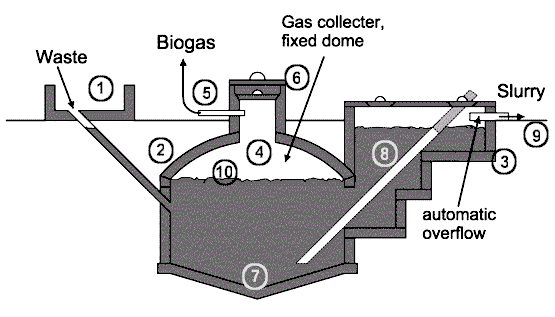
The basic elements of a fixed dome plant (here the '''Nicarao Design''') are shown in the figure below. | The basic elements of a fixed dome plant (here the '''Nicarao Design''') are shown in the figure below. | ||
| − | {| cellspacing="0" cellpadding="0" border="0" | + | {| class="FCK__ShowTableBorders" cellspacing="0" cellpadding="0" border="0" |
|- | |- | ||
| − | | width="45%" | <br> | + | | width="45%" | <br> |
| − | | [[Image:Nicarao biogas.gif]] <small class="IMGLEGEND"> | + | | [[Image:Nicarao biogas.gif]] <small class="IMGLEGEND">Fixed dome plant Nicarao design''': 1. Mixing tank with inlet pipe and sand trap. 2. Digester. 3. Compensation and removal tank. 4. Gasholder. 5. Gaspipe. 6. Entry hatch, with gastight seal. 7. Accumulation of thick sludge. 8. Outlet pipe. 9. Reference level. 10. Supernatant scum, broken up by varying level.'''<br></small><small class="IMGSOURCE">''Source: TBW''</small> |
| width="45%" | <br> | | width="45%" | <br> | ||
|} | |} | ||
| − | {| | + | {| class="IMGright FCK__ShowTableBorders" style="width: 397px; height: 472px" cellpadding="10" align="left" border="0" |
|- | |- | ||
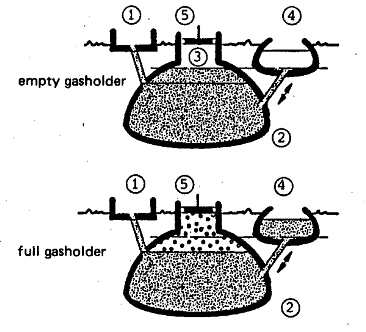
| − | | [[Image:Fixdomscheme.gif]] <small class="IMGLEGEND">'''Basic function of a fixed-dome biogas plant, 1 Mixing pit, 2 Digester, 3 Gasholder, 4 Displacement pit, 5 Gas pipe'''<br> </small><small class="IMGSOURCE">''Source: OEKOTOP''</small> <br> | + | | [[Image:Fixdomscheme.gif]] <small class="IMGLEGEND">'''Basic function of a fixed-dome biogas plant, 1 Mixing pit, 2 Digester, 3 Gasholder, 4 Displacement pit, 5 Gas pipe'''<br></small><small class="IMGSOURCE">''Source: OEKOTOP''</small> <br> |
|} | |} | ||
| − | <br> | + | <br> |
=== Function === | === Function === | ||
| − | A fixed-dome plant comprises of a closed, dome-shaped digester with an immovable, rigid gas-holder and a displacement pit, also named 'compensation tank'. The gas is stored in the upper part of the digester. When gas production commences, the slurry is displaced into the compensating tank. Gas pressure increases with the volume of gas stored, i.e. with the height difference between the two slurry levels. If there is little gas in the gas-holder, the gas pressure is low. <br><br> | + | A fixed-dome plant comprises of a closed, dome-shaped digester with an immovable, rigid gas-holder and a displacement pit, also named 'compensation tank'. The gas is stored in the upper part of the digester. When gas production commences, the slurry is displaced into the compensating tank. Gas pressure increases with the volume of gas stored, i.e. with the height difference between the two slurry levels. If there is little gas in the gas-holder, the gas pressure is low. <br><br> |
=== Digester === | === Digester === | ||
| Line 54: | Line 54: | ||
Fixed dome plants produce just as much gas as floating-drum plants, ''if they are gas-tight''. However, utilization of the gas is less effective as the gas pressure fluctuates substantially. Burners and other simple appliances cannot be set in an optimal way. If the gas is required at constant pressure (e.g., for engines), a gas pressure regulator or a floating gas-holder is necessary. | Fixed dome plants produce just as much gas as floating-drum plants, ''if they are gas-tight''. However, utilization of the gas is less effective as the gas pressure fluctuates substantially. Burners and other simple appliances cannot be set in an optimal way. If the gas is required at constant pressure (e.g., for engines), a gas pressure regulator or a floating gas-holder is necessary. | ||
| − | {| | + | {| class="FCK__ShowTableBorders" style="width: 366px; height: 333px" cellpadding="10" align="right" border="0" |
|- | |- | ||
| | | | ||
<small class="IMGLEGEND">'''[[Image:Biogastunesia01.jpg]]'''</small> | <small class="IMGLEGEND">'''[[Image:Biogastunesia01.jpg]]'''</small> | ||
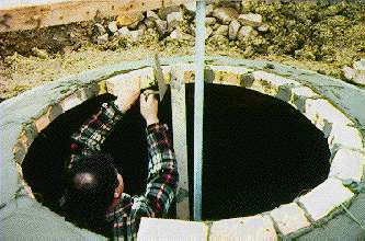
| − | <small class="IMGLEGEND">'''Fixed-dome plant in Tunesia. The final layers of the masonry structure are being fixed.'''<br> </small><small class="IMGSOURCE">''Photo: gtz/GATE''</small> | + | <small class="IMGLEGEND">'''Fixed-dome plant in Tunesia. The final layers of the masonry structure are being fixed.'''<br></small><small class="IMGSOURCE">''Photo: gtz/GATE''</small> |
|} | |} | ||
| − | <br><br><br> | + | <br><br><br> |
=== Gas-Holder === | === Gas-Holder === | ||
| Line 69: | Line 69: | ||
The top part of a fixed-dome plant (the gas space) must be gas-tight. Concrete, masonry and cement rendering are not gas-tight. The gas space must therefore be painted with a [[Plasters and coats for digesters and gas-holder|gas-tight layer]] (e.g. 'Water-proofer', Latex or synthetic paints). A possibility to reduce the risk of cracking of the gas-holder consists in the construction of a [[Optional Parts of a biogas plant#Weak_ring|weak-ring]] in the masonry of the digester. This "ring" is a flexible joint between the lower (water-proof) and the upper (gas-proof) part of the hemispherical structure. It prevents cracks that develop due to the hydrostatic pressure in the lower parts to move into the upper parts of the gas-holder. | The top part of a fixed-dome plant (the gas space) must be gas-tight. Concrete, masonry and cement rendering are not gas-tight. The gas space must therefore be painted with a [[Plasters and coats for digesters and gas-holder|gas-tight layer]] (e.g. 'Water-proofer', Latex or synthetic paints). A possibility to reduce the risk of cracking of the gas-holder consists in the construction of a [[Optional Parts of a biogas plant#Weak_ring|weak-ring]] in the masonry of the digester. This "ring" is a flexible joint between the lower (water-proof) and the upper (gas-proof) part of the hemispherical structure. It prevents cracks that develop due to the hydrostatic pressure in the lower parts to move into the upper parts of the gas-holder. | ||
| − | <br><br><br><br><br><br><br> | + | <br><br><br><br><br><br><br> |
=== Types of fixed-dome plants === | === Types of fixed-dome plants === | ||
| − | {| | + | {| class="IMGright FCK__ShowTableBorders" cellpadding="10" width="259" align="right" border="0" |
|- | |- | ||
| − | | <small class="IMGLEGEND">'''Chinese fixed dome plant'''<br> </small><small class="IMGSOURCE">''Source: TBW''</small> <br> | + | | <small class="IMGLEGEND">'''Chinese fixed dome plant'''<br></small><small class="IMGSOURCE">''Source: TBW''</small> <br> |
|} | |} | ||
| Line 83: | Line 83: | ||
*'''CAMARTEC model''' has a simplified structure of a hemispherical dome shell based on a rigid foundation ring only and a calculated joint of fraction, the so-called weak / strong ring. It[[Image:Chinafixdome.gif]] was developed in the late 80s in [[Biogas technology in Tanzania|Tanzania]]. | *'''CAMARTEC model''' has a simplified structure of a hemispherical dome shell based on a rigid foundation ring only and a calculated joint of fraction, the so-called weak / strong ring. It[[Image:Chinafixdome.gif]] was developed in the late 80s in [[Biogas technology in Tanzania|Tanzania]]. | ||
| − | <br> | + | <br> |
| − | <br> | + | <br> |
| − | {| cellspacing="0" cellpadding="0" border="0 | + | {| class="IMGcenter FCK__ShowTableBorders" cellspacing="0" cellpadding="0" border="0" |
|- | |- | ||
| − | | width="45%" | <br> | + | | width="45%" | <br> |
| − | | [[Image:Camartecfixdome.gif]]<small class="IMGLEGEND">'''Fixed dome plant CAMARTEC design'''<br> </small><small class="IMGSOURCE">''Source: TBW''</small> | + | | [[Image:Camartecfixdome.gif]]<small class="IMGLEGEND">'''Fixed dome plant CAMARTEC design'''<br></small><small class="IMGSOURCE">''Source: TBW''</small> |
| width="45%" | <br> | | width="45%" | <br> | ||
|} | |} | ||
| − | <br> | + | <br> |
=== Climate and size === | === Climate and size === | ||
| Line 106: | Line 106: | ||
Fixed dome plants can be recommended only where construction can be supervised by experienced biogas technicians. | Fixed dome plants can be recommended only where construction can be supervised by experienced biogas technicians. | ||
| − | <br> | + | <br> |
== Floating-drum plants == | == Floating-drum plants == | ||
| − | {| | + | {| class="IMGleft FCK__ShowTableBorders" cellspacing="0" cellpadding="0" align="left" border="0" |
|- | |- | ||
| | | | ||
[[Image:Floating drum mauretania.jpg]] | [[Image:Floating drum mauretania.jpg]] | ||
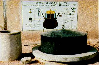
| − | <small class="IMGLEGEND">'''Floating-drum plant in Mauretania'''<br> </small><small class="IMGSOURCE">''Photo: gtz/GATE''</small> <br> | + | <small class="IMGLEGEND">'''Floating-drum plant in Mauretania'''<br></small><small class="IMGSOURCE">''Photo: gtz/GATE''</small> <br> |
|} | |} | ||
| − | <br> | + | <br> |
=== The drum === | === The drum === | ||
| − | In the past, floating-drum plants were mainly built in India. A floating-drum plant consists of a cylindrical or dome-shaped digester and a moving, floating gas-holder, or drum. The gas-holder floats either directly in the fermenting slurry or in a separate water jacket. The drum in which the biogas collects has an internal and/or external guide frame that provides stability and keeps the drum upright. If biogas is produced, the drum moves up, if gas is consumed, the gas-holder sinks back. <br> | + | In the past, floating-drum plants were mainly built in India. A floating-drum plant consists of a cylindrical or dome-shaped digester and a moving, floating gas-holder, or drum. The gas-holder floats either directly in the fermenting slurry or in a separate water jacket. The drum in which the biogas collects has an internal and/or external guide frame that provides stability and keeps the drum upright. If biogas is produced, the drum moves up, if gas is consumed, the gas-holder sinks back. <br> |
| − | <br> | + | <br> |
=== Size === | === Size === | ||
Floating-drum plants are used chiefly for digesting animal and human feces on a continuous-feed mode of operation, i.e. with daily input. They are used most frequently by small- to middle-sized farms (digester size: 5-15m<sup>3</sup>) or in institutions and larger agro-industrial estates (digester size: 20-100m<sup>3</sup>). | Floating-drum plants are used chiefly for digesting animal and human feces on a continuous-feed mode of operation, i.e. with daily input. They are used most frequently by small- to middle-sized farms (digester size: 5-15m<sup>3</sup>) or in institutions and larger agro-industrial estates (digester size: 20-100m<sup>3</sup>). | ||
| − | <blockquote>'''''Advantages''''': Floating-drum plants are easy to understand and operate. They provide gas at a constant pressure, and the stored gas-volume is immediately recognizable by the position of the drum. Gas-tightness is no problem, provided the gasholder is de-rusted and painted regularly. </blockquote> <blockquote> | + | <blockquote>'''''Advantages''''': Floating-drum plants are easy to understand and operate. They provide gas at a constant pressure, and the stored gas-volume is immediately recognizable by the position of the drum. Gas-tightness is no problem, provided the gasholder is de-rusted and painted regularly. </blockquote><blockquote> |
| − | '''''Disadvantages''''': The steel drum is relatively expensive and maintenance-intensive. Removing rust and painting has to be carried out regularly. The life-time of the drum is short (up to 15 years; in tropical coastal regions about five years). If fibrous substrates are used, the gas-holder shows a tendency to get "stuck" in the resultant floating scum. | + | '''''Disadvantages''''': The steel drum is relatively expensive and maintenance-intensive. Removing rust and painting has to be carried out regularly. The life-time of the drum is short (up to 15 years; in tropical coastal regions about five years). If fibrous substrates are used, the gas-holder shows a tendency to get "stuck" in the resultant floating scum. |
| − | </blockquote> | + | </blockquote> |
| − | {| | + | {| class="IMGleft FCK__ShowTableBorders" cellpadding="10" width="300" align="left" border="0" |
|- | |- | ||
| − | | [[Image:Floatdrumschemewaterjack s.gif]]<small class="IMGLEGEND">'''Water-jacket plant with external guide frame. 1 Mixing pit, 11 Fill pipe, 2 Digester, 3 Gasholder, 31 Guide frame, 4 Slurry store, 5 Gas pipe'''<br> </small><small class="IMGSOURCE">''Source: Sasse, 1984''</small> <br> | + | | [[Image:Floatdrumschemewaterjack s.gif]]<small class="IMGLEGEND">'''Water-jacket plant with external guide frame. 1 Mixing pit, 11 Fill pipe, 2 Digester, 3 Gasholder, 31 Guide frame, 4 Slurry store, 5 Gas pipe'''<br></small><small class="IMGSOURCE">''Source: Sasse, 1984''</small> <br> |
|} | |} | ||
| − | <br> | + | <br> |
=== Water-jacket floating-drum plants === | === Water-jacket floating-drum plants === | ||
| − | Water-jacket plants are universally applicable and easy to maintain. The drum cannot get stuck in a scum layer, even if the substrate has a high solids content. Water-jacket plants are characterized by a long useful life and a more aesthetic appearance (no dirty gas-holder). Due to their superior sealing of the substrate (hygiene!), they are recommended for use in the fermentation of night soil. The extra cost of the masonry water jacket is relatively modest. <br> <br> | + | Water-jacket plants are universally applicable and easy to maintain. The drum cannot get stuck in a scum layer, even if the substrate has a high solids content. Water-jacket plants are characterized by a long useful life and a more aesthetic appearance (no dirty gas-holder). Due to their superior sealing of the substrate (hygiene!), they are recommended for use in the fermentation of night soil. The extra cost of the masonry water jacket is relatively modest. <br><br> |
=== Material of digester and drum === | === Material of digester and drum === | ||
| Line 150: | Line 150: | ||
Floating-drums made of glass-fiber reinforced plastic and high-density polyethylene have been used successfully, but the construction costs are higher compared to using steel. Floating-drums made of wire-mesh-reinforced concrete are liable to hairline cracking and are intrinsically porous. They require a gas-tight, elastic internal coating. PVC drums are unsuitable because they are not resistant to UV. | Floating-drums made of glass-fiber reinforced plastic and high-density polyethylene have been used successfully, but the construction costs are higher compared to using steel. Floating-drums made of wire-mesh-reinforced concrete are liable to hairline cracking and are intrinsically porous. They require a gas-tight, elastic internal coating. PVC drums are unsuitable because they are not resistant to UV. | ||
| − | <br> | + | <br> |
=== Guide frame === | === Guide frame === | ||
| Line 158: | Line 158: | ||
The floating gas drum can be replaced by a balloon above the digester. This reduces construction costs but in practice problems always arise with the attachment of the balloon to the digester and with the high susceptibility to physical damage. | The floating gas drum can be replaced by a balloon above the digester. This reduces construction costs but in practice problems always arise with the attachment of the balloon to the digester and with the high susceptibility to physical damage. | ||
| − | <br> | + | <br> |
=== Types of floating-drum plants === | === Types of floating-drum plants === | ||
| Line 171: | Line 171: | ||
*'''BORDA model: '''The BORDA-plant combines the static advantages of hemispherical digester with the process-stability of the floating-drum and the longer life span of a water jacket plant. | *'''BORDA model: '''The BORDA-plant combines the static advantages of hemispherical digester with the process-stability of the floating-drum and the longer life span of a water jacket plant. | ||
| − | <br> | + | <br> |
=== Further reading: === | === Further reading: === | ||
| Line 184: | Line 184: | ||
*Werner, U., St�hr, U., Hees, N. - GATE: Biogas Plants in Animal Husbandry - A Practical Guide. Friedr. Vieweg & Sohn, Braunschweig/Wiesbaden (Germany), 1989; 153 p., ISBN: 3-528-02048-2 | *Werner, U., St�hr, U., Hees, N. - GATE: Biogas Plants in Animal Husbandry - A Practical Guide. Friedr. Vieweg & Sohn, Braunschweig/Wiesbaden (Germany), 1989; 153 p., ISBN: 3-528-02048-2 | ||
| − | + | ||
*Sasse, L. - Centro de Investigacion, Estudios y Documentacion (CIED) Lima (Peru): La Planta de Biogas - Bosquejo y Detaille de Plantas Simples. Reciclaje de la Materia Organica 3. 1986. 103 p. | *Sasse, L. - Centro de Investigacion, Estudios y Documentacion (CIED) Lima (Peru): La Planta de Biogas - Bosquejo y Detaille de Plantas Simples. Reciclaje de la Materia Organica 3. 1986. 103 p. | ||
| Line 194: | Line 194: | ||
*Werner, U.; St�hr, U.; Hees, N.: Praktischer Leitfaden für Biogasanlagen in der Tierproduktion. Sonderpublikation der GTZ Nr. 180. 1986. ISBN: 3-88085-311-8 | *Werner, U.; St�hr, U.; Hees, N.: Praktischer Leitfaden für Biogasanlagen in der Tierproduktion. Sonderpublikation der GTZ Nr. 180. 1986. ISBN: 3-88085-311-8 | ||
| − | <br> | + | <br> |
== Low-Cost Polyethylen Tube Digester == | == Low-Cost Polyethylen Tube Digester == | ||
| Line 202: | Line 202: | ||
---- | ---- | ||
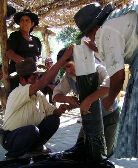
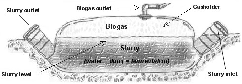
| − | In the case of the Low-Cost Polyethylene Tube Digester model which is applied in [[Low-Cost Polyethylene Tube Digesters in Bolivia|Bolivia]] (Peru, Ecuador, Colombia, Centro America and Mexico), the tubular polyethylene film (two coats of 300 microns) is bended at each end around a 6 inch PVC drainpipe and is wound with rubber strap of recycled tire-tubes. With this system a hermetic isolated tank is obtained (figure td1). <br> | + | In the case of the Low-Cost Polyethylene Tube Digester model which is applied in [[Low-Cost Polyethylene Tube Digesters in Bolivia|Bolivia]] (Peru, Ecuador, Colombia, Centro America and Mexico), the tubular polyethylene film (two coats of 300 microns) is bended at each end around a 6 inch PVC drainpipe and is wound with rubber strap of recycled tire-tubes. With this system a hermetic isolated tank is obtained (figure td1). <br> |
| − | {| cellspacing="1" cellpadding="1 | + | {| class="FCK__ShowTableBorders" cellspacing="1" cellpadding="1" align="center" border="0" |
|- | |- | ||
| width="520" | | | width="520" | | ||
| − | [[Image:In Outlet winding Tube Digester.jpg|276x337px]]<br> | + | [[Image:In Outlet winding Tube Digester.jpg|276x337px|In Outlet winding Tube Digester.jpg]]<br> |
| − | Picture td2: Winding In-/Outlet Tube Digester<br>'''''Source: GTZ / EnDev Bolivia'''''<br> | + | Picture td2: Winding In-/Outlet Tube Digester<br>'''''Source: GTZ / EnDev Bolivia'''''<br> |
| width="520" | | | width="520" | | ||
| − | <br> | + | <br> |
| − | [[Image:Low Cost Polyethylene Tube Digester Scheme.jpg| | + | [[Image:Low Cost Polyethylene Tube Digester Scheme.jpg|509x268px|Low Cost Polyethylene Tube Digester Scheme.jpg]] |
| − | Figure td1: Scheme of Low-Cost Polyethylene Tube Digester<br>'''''<span lang="EN-US" style="font-size: 10pt; line-height: 115% | + | Figure td1: Scheme of Low-Cost Polyethylene Tube Digester<br>'''''<span lang="EN-US" style="font-size: 10pt; line-height: 115%">Source: GTZ / EnDev Bolivia</span>''''' |
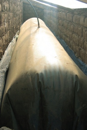
| − | One of the 6" PVC drainpipes serves as inlet and the other one as the outlet of the slurry. In the tube digester finally, a hydraulic level is set up by itself, so that as much quantity of added prime matter (the mix of dung and water) as quantity of fertilizer leave by the outlet.<br>Because the tubular polyethylene is flexible, it is necessary to construct a "cradle" which will accommodate the reaction tank, so that a trench is excavated (picture td3).<br> | + | One of the 6" PVC drainpipes serves as inlet and the other one as the outlet of the slurry. In the tube digester finally, a hydraulic level is set up by itself, so that as much quantity of added prime matter (the mix of dung and water) as quantity of fertilizer leave by the outlet.<br>Because the tubular polyethylene is flexible, it is necessary to construct a "cradle" which will accommodate the reaction tank, so that a trench is excavated (picture td3).<br> |
|- | |- | ||
| Line 228: | Line 228: | ||
The capacity of the gasholder corresponds to 1/4 of the total capacity of the reaction tube (figure td1). | The capacity of the gasholder corresponds to 1/4 of the total capacity of the reaction tube (figure td1). | ||
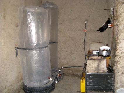
| − | To overcome the problem of low gas flow rates, two 200 microns tubular polyethylene reservoirs are installed close to the kitchen, which gives a 1,3 m³ additional gas storage (picture td4).<br> | + | To overcome the problem of low gas flow rates, two 200 microns tubular polyethylene reservoirs are installed close to the kitchen, which gives a 1,3 m³ additional gas storage (picture td4).<br> |
| − | [[Image:Gas Storage Reservoir double inside.jpg| | + | [[Image:Gas Storage Reservoir double inside.jpg|424x318px|Gas Storage Reservoir double inside.jpg]] |
| − | Picture td4: Gas Storage Reservoir<br> '''''Source: GTZ / EnDev Bolivia''''' | + | Picture td4: Gas Storage Reservoir<br>'''''Source: GTZ / EnDev Bolivia''''' |
| − | | width="520" | [[Image:Biodigestor familiar bolivia altiplano.jpg| | + | | width="520" | [[Image:Biodigestor familiar bolivia altiplano.jpg|293x434px|Biodigestor familiar bolivia altiplano.jpg]] |
| − | Picture td3: Tube Digester - Bolivia Altiplano'''''<br> Source: GTZ / EnDev Bolivia''''' | + | Picture td3: Tube Digester - Bolivia Altiplano'''''<br> Source: GTZ / EnDev Bolivia''''' |
|- | |- | ||
| Line 245: | Line 245: | ||
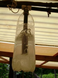
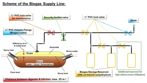
The track of biogas up to the kitchen is realised directly. The digester system works with a biogas pressure between 15 - 20 cm water column. A security valve, which is constructed of a 1, 5 l or 2, 0 l PET refreshment bottle (picture td5), controlls the pressure. For the supply line a 1/2" flexible PVC tube is used. | The track of biogas up to the kitchen is realised directly. The digester system works with a biogas pressure between 15 - 20 cm water column. A security valve, which is constructed of a 1, 5 l or 2, 0 l PET refreshment bottle (picture td5), controlls the pressure. For the supply line a 1/2" flexible PVC tube is used. | ||
| − | <br> | + | <br> |
| − | [[Image:Tube Digester Security Valve.jpg| | + | [[Image:Tube Digester Security Valve.jpg|196x261px|Tube Digester Security Valve.jpg]] |
| − | Picture td5: Tube Digester Security Valve<br>'''''Source: GTZ / EnDev Bolivia''''' | + | Picture td5: Tube Digester Security Valve<br>'''''Source: GTZ / EnDev Bolivia''''' |
| − | | width="520" | '''''[[Image:Scheme of the biogas supply line tube digester.jpg| | + | | width="520" | '''''[[Image:Scheme of the biogas supply line tube digester.jpg|516x293px|Scheme of the biogas supply line tube digester.jpg]]''''' |
| − | Figure td6: Scheme of the gas supply line''<br>'''Source: GTZ / EnDev Bolivia''''' | + | Figure td6: Scheme of the gas supply line''<br>'''Source: GTZ / EnDev Bolivia''''' |
|} | |} | ||
| − | ==== '''''Modification'''''<b><br></b> | + | ==== '''''Modification'''''<b><br></b> ==== |
---- | ---- | ||
| − | To be able to work in different altitudes and climate zones, in Bolivia the Low-Cost Polyethylene Tube Digester was modified into three climate types.<br>The three implanted types are calculated for 4 - 5 hours of Biogas using per day. The digesters differ in size and protection of the system. <br> | + | To be able to work in different altitudes and climate zones, in Bolivia the Low-Cost Polyethylene Tube Digester was modified into three climate types.<br>The three implanted types are calculated for 4 - 5 hours of Biogas using per day. The digesters differ in size and protection of the system. <br> |
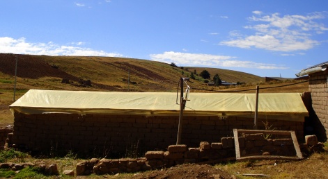
| − | The biodigester for the Bolivian Altiplano (picture td7) is enclosed in a greenhouse of polyethylene (250 microns), supported by two lateral adobe walls of 40 cm thickness above the hole length of the trench. This lateral walls accumulate the heat of the greenhouse effect, that with freezing temperatures during winter nights, they maintain the digester in function, by the own high thermal inertia. So it is possible to realise the installation of a working digester in an altitude of more than 4.500 m about sea level. <br> | + | The biodigester for the Bolivian Altiplano (picture td7) is enclosed in a greenhouse of polyethylene (250 microns), supported by two lateral adobe walls of 40 cm thickness above the hole length of the trench. This lateral walls accumulate the heat of the greenhouse effect, that with freezing temperatures during winter nights, they maintain the digester in function, by the own high thermal inertia. So it is possible to realise the installation of a working digester in an altitude of more than 4.500 m about sea level. <br> |
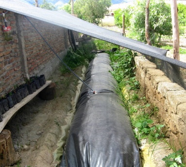
| − | For the digesters in the valley and tropical zones (picture td8) there is no need to install a greenhouse, but it is to protect the polyethylene of the biodigester about the direct solar radiation with a half shade red or better a roof. Additional it is recommended to protect this systems with a wire-mesh fence against animals like e.g. cows or chickens.<br> | + | For the digesters in the valley and tropical zones (picture td8) there is no need to install a greenhouse, but it is to protect the polyethylene of the biodigester about the direct solar radiation with a half shade red or better a roof. Additional it is recommended to protect this systems with a wire-mesh fence against animals like e.g. cows or chickens.<br> |
| − | {| cellspacing="1" cellpadding="1" border="0 | + | {| class="FCK__ShowTableBorders" style="width: 975px; height: 322px" cellspacing="1" cellpadding="1" border="0" |
|- | |- | ||
| width="520" | | | width="520" | | ||
| − | [[Image:Low Cost Tube Digester Altiplano.JPG| | + | [[Image:Low Cost Tube Digester Altiplano.JPG|471x258px|Low Cost Tube Digester Altiplano.JPG]]<br> |
| − | Picture td7: Low-Cost Tube Digester Altiplano of Bolivia<br>'''''Source: GTZ / EnDev Bolivia''''' | + | Picture td7: Low-Cost Tube Digester Altiplano of Bolivia<br>'''''Source: GTZ / EnDev Bolivia''''' |
| width="520" | | | width="520" | | ||
| − | [[Image:Low Cost Tube Digester Valley.JPG| | + | [[Image:Low Cost Tube Digester Valley.JPG|383x344px|Low Cost Tube Digester Valley.JPG]]<br> |
| − | Picture td8: Low-Cost Tube Digester - Valley<br>'''''Source: GTZ / EnDev Bolivia''''' | + | Picture td8: Low-Cost Tube Digester - Valley<br>'''''Source: GTZ / EnDev Bolivia''''' |
|} | |} | ||
| − | <br> | + | <br> |
| − | |||
| − | |||
| − | |||
| − | |||
| − | |||
| + | === [[Experience with Polyethylene Biogas Digester (PBD) from some countries|Experience with Polyethylene Biogas Digester (PBD) from some countries]]<br> === | ||
= Biogas Plant Types and Design = | = Biogas Plant Types and Design = | ||
| Line 292: | Line 288: | ||
== Digester types in industrialized countries == | == Digester types in industrialized countries == | ||
| − | {| | + | {| class="IMGright FCK__ShowTableBorders" cellpadding="10" width="378" align="right" border="0" |
|- | |- | ||
| − | | [[Image:Indsolcontrol.jpg]]<small class="IMGLEGEND">'''Control glasses for an industrial digester for solid organic waste, TBW, Germany'''<br> </small><br> | + | | [[Image:Indsolcontrol.jpg]]<small class="IMGLEGEND">'''Control glasses for an industrial digester for solid organic waste, TBW, Germany'''<br></small><br> |
|} | |} | ||
| Line 309: | Line 305: | ||
'''Gas use element''' is in Europe in 95% of the cases a thermo-power unit which produces electricity for the farm, the grid and heat for the house, greenhouses and other uses. The thermo-power unit has the advantage, that the required energy can be produced in any mixture of gas and fossil energy. It can, therefore, react to periods of low gas production and high energy requirements or vice versa. | '''Gas use element''' is in Europe in 95% of the cases a thermo-power unit which produces electricity for the farm, the grid and heat for the house, greenhouses and other uses. The thermo-power unit has the advantage, that the required energy can be produced in any mixture of gas and fossil energy. It can, therefore, react to periods of low gas production and high energy requirements or vice versa. | ||
| − | {| cellspacing="0" cellpadding="0" border="0 | + | {| class="IMGcenter FCK__ShowTableBorders" cellspacing="0" cellpadding="0" border="0" |
|- | |- | ||
| − | | width="45%" | <br> | + | | width="45%" | <br> |
| − | | [[Image:Concretedigest1.gif]]<small class="IMGLEGEND">'''Concrete digester with two chambers (one heated, one unheated for storage)'''<br> </small><small class="IMGSOURCE">''Source: TBW''</small> | + | | [[Image:Concretedigest1.gif]]<small class="IMGLEGEND">'''Concrete digester with two chambers (one heated, one unheated for storage)'''<br></small><small class="IMGSOURCE">''Source: TBW''</small> |
| width="45%" | <br> | | width="45%" | <br> | ||
|} | |} | ||
| − | {| cellspacing="0" cellpadding="0" border="0 | + | {| class="IMGcenter FCK__ShowTableBorders" cellspacing="0" cellpadding="0" border="0" |
|- | |- | ||
| − | | width="45%" | <br> | + | | width="45%" | <br> |
| − | | [[Image:Concretedigest2.gif]]<small class="IMGLEGEND">'''Concrete digester with integrated plastic gas-holder'''<br> </small><small class="IMGSOURCE">''Photo: TBW''</small> | + | | [[Image:Concretedigest2.gif]]<small class="IMGLEGEND">'''Concrete digester with integrated plastic gas-holder'''<br></small><small class="IMGSOURCE">''Photo: TBW''</small> |
| width="45%" | <br> | | width="45%" | <br> | ||
|} | |} | ||
| − | {| cellspacing="0" cellpadding="0" border="0 | + | {| class="IMGcenter FCK__ShowTableBorders" cellspacing="0" cellpadding="0" border="0" |
|- | |- | ||
| − | | width="45%" | <br> | + | | width="45%" | <br> |
| − | | [[Image:Concretedigest3.gif]]<small class="IMGLEGEND">'''Steelvessel fermenter with seperate ballon gas-holder'''<br> </small><small class="IMGSOURCE">''Photo: TBW''</small> | + | | [[Image:Concretedigest3.gif]]<small class="IMGLEGEND">'''Steelvessel fermenter with seperate ballon gas-holder'''<br></small><small class="IMGSOURCE">''Photo: TBW''</small> |
| width="45%" | <br> | | width="45%" | <br> | ||
|} | |} | ||
| Line 353: | Line 349: | ||
Horizontal biogas plants are usually chosen when shallow installation is called for (groundwater, rock). They are made of masonry or concrete. | Horizontal biogas plants are usually chosen when shallow installation is called for (groundwater, rock). They are made of masonry or concrete. | ||
| − | <blockquote>'''''Advantages''''': Shallow construction despite large slurry space. </blockquote> <blockquote> | + | <blockquote>'''''Advantages''''': Shallow construction despite large slurry space. </blockquote><blockquote> |
| − | '''''Disadvantages''''': Problems with gas-space leakage, difficult elimination of scum. | + | '''''Disadvantages''''': Problems with gas-space leakage, difficult elimination of scum. |
| − | </blockquote> | + | </blockquote> |
== Earth-pit plants == | == Earth-pit plants == | ||
Masonry digesters are not necessary in stable soil (e.g. laterite). It is sufficient to line the pit with a thin layer of cement (wire-mesh fixed to the pit wall and plastered) in order to prevent seepage. The edge of the pit is reinforced with a ring of masonry that also serves as anchorage for the gas-holder. The gas-holder can be made of metal or plastic sheeting. If plastic sheeting is used, it must be attached to a quadratic wooden frame that extends down into the slurry and is anchored in place to counter its buoyancy. The requisite gas pressure is achieved by placing weights on the gas-holder. An overflow point in the peripheral wall serves as the slurry outlet. | Masonry digesters are not necessary in stable soil (e.g. laterite). It is sufficient to line the pit with a thin layer of cement (wire-mesh fixed to the pit wall and plastered) in order to prevent seepage. The edge of the pit is reinforced with a ring of masonry that also serves as anchorage for the gas-holder. The gas-holder can be made of metal or plastic sheeting. If plastic sheeting is used, it must be attached to a quadratic wooden frame that extends down into the slurry and is anchored in place to counter its buoyancy. The requisite gas pressure is achieved by placing weights on the gas-holder. An overflow point in the peripheral wall serves as the slurry outlet. | ||
| − | <blockquote>'''''Advantages''''': Low cost of installation (as little as 20% of a floating-drum plant); high potential for self help approaches. </blockquote> <blockquote> | + | <blockquote>'''''Advantages''''': Low cost of installation (as little as 20% of a floating-drum plant); high potential for self help approaches. </blockquote><blockquote> |
| − | '''''Disadvantages''''': Short useful life; serviceable only in suitable, impermeable types of soil. | + | '''''Disadvantages''''': Short useful life; serviceable only in suitable, impermeable types of soil. |
| − | </blockquote> | + | </blockquote> |
Earth-pit plants can only be recommended for installation in impermeable soil located above the groundwater table. Their construction is particularly inexpensive in connection with plastic sheet gas-holders. | Earth-pit plants can only be recommended for installation in impermeable soil located above the groundwater table. Their construction is particularly inexpensive in connection with plastic sheet gas-holders. | ||
| Line 367: | Line 363: | ||
The ferro-cement type of construction can be applied either as a self-supporting shell or an earth-pit lining. The vessel is usually cylindrical. Very small plants (Volume under 6 m<sup>3</sup>) can be prefabricated. As in the case of a fixed-dome plant, the ferrocement gasholder requires special sealing measures (proven reliability with cemented-on aluminium foil). | The ferro-cement type of construction can be applied either as a self-supporting shell or an earth-pit lining. The vessel is usually cylindrical. Very small plants (Volume under 6 m<sup>3</sup>) can be prefabricated. As in the case of a fixed-dome plant, the ferrocement gasholder requires special sealing measures (proven reliability with cemented-on aluminium foil). | ||
| − | <blockquote>'''''Advantages''''': Low cost of construction, especially in comparison with potentially high cost of masonry for alternative plants; mass production possible; low material input. </blockquote> <blockquote> | + | <blockquote>'''''Advantages''''': Low cost of construction, especially in comparison with potentially high cost of masonry for alternative plants; mass production possible; low material input. </blockquote><blockquote> |
| − | '''''Disadvantages''''': Substantial consumption of essentially good-quality cement; workmanship must meet high quality standards; uses substantial amounts of expensive wire mesh; construction technique not yet adequately time-tested; special sealing measures for the gas-holder are necessary. | + | '''''Disadvantages''''': Substantial consumption of essentially good-quality cement; workmanship must meet high quality standards; uses substantial amounts of expensive wire mesh; construction technique not yet adequately time-tested; special sealing measures for the gas-holder are necessary. |
| − | </blockquote> | + | </blockquote> |
| − | Ferro-cement biogas plants are only recommended in cases where special ferro-cement know-how is available. <!-- Navigation Footer --> <br> | + | Ferro-cement biogas plants are only recommended in cases where special ferro-cement know-how is available. <!-- Navigation Footer --><br> |
| − | <br> | + | <br> |
| − | <br> <br> | + | <br><br> |
[[Biogas|back to "Biogas" section]] | [[Biogas|back to "Biogas" section]] | ||
| + | |||
<br></div></div> | <br></div></div> | ||
| − | + | [[Category:Biogas]] [[Category:Bolivia]] | |
| − | [[Category:Biogas]] | ||
| − | [[Category:Bolivia | ||
| − | |||
Revision as of 06:10, 7 June 2010
Biogas - Digester types
In this chapter, the most important types of biogas plants are described:
- Fixed-dome plants
- Floating-drum plants
- Low-Cost Polyethylene Tube Digester
- Balloon plants
- Horizontal plants
- Earth-pit plants
- Ferrocement plants
- ARTI Biogas Plant
Of these, the two most familiar types in developing countries are the fixed-dome plants and the floating-drum plants. Typical designs in industrialized countries and appropriate design selection criteria have also been considered.
Fixed-dome plants
The costs of a fixed-dome biogas plant are relatively low. It is simple as no moving parts exist. There are also no rusting steel parts and hence a long life of the plant (20 years or more) can be expected. The plant is constructed underground, protecting it from physical damage and saving space. While the underground digester is protected from low temperatures at night and during cold seasons, sunshine and warm seasons take longer to heat up the digester. No day/night fluctuations of temperature in the digester positively influence the bacteriological processes.
The construction of fixed dome plants is labor-intensive, thus creating local employment. Fixed-dome plants are not easy to build. They should only be built where construction can be supervised by experienced biogas technicians. Otherwise plants may not be gas-tight (porosity and cracks).
The basic elements of a fixed dome plant (here the Nicarao Design) are shown in the figure below.
 Basic function of a fixed-dome biogas plant, 1 Mixing pit, 2 Digester, 3 Gasholder, 4 Displacement pit, 5 Gas pipe Basic function of a fixed-dome biogas plant, 1 Mixing pit, 2 Digester, 3 Gasholder, 4 Displacement pit, 5 Gas pipeSource: OEKOTOP |
Function
A fixed-dome plant comprises of a closed, dome-shaped digester with an immovable, rigid gas-holder and a displacement pit, also named 'compensation tank'. The gas is stored in the upper part of the digester. When gas production commences, the slurry is displaced into the compensating tank. Gas pressure increases with the volume of gas stored, i.e. with the height difference between the two slurry levels. If there is little gas in the gas-holder, the gas pressure is low.
Digester
The digesters of fixed-dome plants are usually masonry structures, structures of cement and ferro-cement exist. Main parameters for the choice of material are:
- Technical suitability (stability, gas- and liquid tightness);
- cost-effectiveness;
- availability in the region and transport costs;
- availability of local skills for working with the particular building material.
Fixed dome plants produce just as much gas as floating-drum plants, if they are gas-tight. However, utilization of the gas is less effective as the gas pressure fluctuates substantially. Burners and other simple appliances cannot be set in an optimal way. If the gas is required at constant pressure (e.g., for engines), a gas pressure regulator or a floating gas-holder is necessary.
|
Fixed-dome plant in Tunesia. The final layers of the masonry structure are being fixed. |
Gas-Holder
The top part of a fixed-dome plant (the gas space) must be gas-tight. Concrete, masonry and cement rendering are not gas-tight. The gas space must therefore be painted with a gas-tight layer (e.g. 'Water-proofer', Latex or synthetic paints). A possibility to reduce the risk of cracking of the gas-holder consists in the construction of a weak-ring in the masonry of the digester. This "ring" is a flexible joint between the lower (water-proof) and the upper (gas-proof) part of the hemispherical structure. It prevents cracks that develop due to the hydrostatic pressure in the lower parts to move into the upper parts of the gas-holder.
Types of fixed-dome plants
| Chinese fixed dome plant Source: TBW |
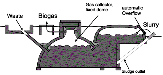
- Chinese fixed-dome plant is the archetype of all fixed dome plants. Several million have been constructed in China. The digester consists of a cylinder with round bottom and top.
- Janata model was the first fixed-dome design in India, as a response to the Chinese fixed dome plant. It is not constructed anymore. The mode of construction lead to cracks in the gasholder - very few of these plant had been gas-tight.
- Deenbandhu, the successor of the Janata plant in India, with improved design, was more crack-proof and consumed less building material than the Janata plant. with a hemisphere digester
- CAMARTEC model has a simplified structure of a hemispherical dome shell based on a rigid foundation ring only and a calculated joint of fraction, the so-called weak / strong ring. ItFile:Chinafixdome.gif was developed in the late 80s in Tanzania.
 Fixed dome plant CAMARTEC design Fixed dome plant CAMARTEC designSource: TBW |
Climate and size
Fixed-dome plants must be covered with earth up to the top of the gas-filled space to counteract the internal pressure (up to 0,15 bar). The earth cover insulation and the option for internal heating makes them suitable for colder climates. Due to economic parameters, the recommended minimum size of a fixed-dome plant is 5 m3. Digester volumes up to 200 m3 are known and possible.
Advantages: Low initial costs and long useful life-span; no moving or rusting parts involved; basic design is compact, saves space and is well insulated; construction creates local employment.
Disadvantages: Masonry gas-holders require special sealants and high technical skills for gas-tight construction; gas leaks occur quite frequently; fluctuating gas pressure complicates gas utilization; amount of gas produced is not immediately visible, plant operation not readily understandable; fixed dome plants need exact planning of levels; excavation can be difficult and expensive in bedrock. </div>
Fixed dome plants can be recommended only where construction can be supervised by experienced biogas technicians.
Floating-drum plants
|
Floating-drum plant in Mauretania |
The drum
In the past, floating-drum plants were mainly built in India. A floating-drum plant consists of a cylindrical or dome-shaped digester and a moving, floating gas-holder, or drum. The gas-holder floats either directly in the fermenting slurry or in a separate water jacket. The drum in which the biogas collects has an internal and/or external guide frame that provides stability and keeps the drum upright. If biogas is produced, the drum moves up, if gas is consumed, the gas-holder sinks back.
Size
Floating-drum plants are used chiefly for digesting animal and human feces on a continuous-feed mode of operation, i.e. with daily input. They are used most frequently by small- to middle-sized farms (digester size: 5-15m3) or in institutions and larger agro-industrial estates (digester size: 20-100m3).
Advantages: Floating-drum plants are easy to understand and operate. They provide gas at a constant pressure, and the stored gas-volume is immediately recognizable by the position of the drum. Gas-tightness is no problem, provided the gasholder is de-rusted and painted regularly.
Disadvantages: The steel drum is relatively expensive and maintenance-intensive. Removing rust and painting has to be carried out regularly. The life-time of the drum is short (up to 15 years; in tropical coastal regions about five years). If fibrous substrates are used, the gas-holder shows a tendency to get "stuck" in the resultant floating scum.
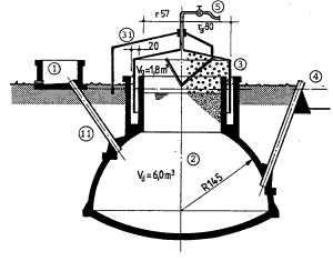 Water-jacket plant with external guide frame. 1 Mixing pit, 11 Fill pipe, 2 Digester, 3 Gasholder, 31 Guide frame, 4 Slurry store, 5 Gas pipe Water-jacket plant with external guide frame. 1 Mixing pit, 11 Fill pipe, 2 Digester, 3 Gasholder, 31 Guide frame, 4 Slurry store, 5 Gas pipeSource: Sasse, 1984 |
Water-jacket floating-drum plants
Water-jacket plants are universally applicable and easy to maintain. The drum cannot get stuck in a scum layer, even if the substrate has a high solids content. Water-jacket plants are characterized by a long useful life and a more aesthetic appearance (no dirty gas-holder). Due to their superior sealing of the substrate (hygiene!), they are recommended for use in the fermentation of night soil. The extra cost of the masonry water jacket is relatively modest.
Material of digester and drum
The digester is usually made of brick, concrete or quarry-stone masonry with plaster. The gas drum normally consists of 2.5 mm steel sheets for the sides and 2 mm sheets for the top. It has welded-in braces which break up surface scum when the drum rotates. The drum must be protected against corrosion. Suitable coating products are oil paints, synthetic paints and bitumen paints. Correct priming is important. There must be at least two preliminary coats and one topcoat. Coatings of used oil are cheap. They must be renewed monthly. Plastic sheeting stuck to bitumen sealant has not given good results. In coastal regions, repainting is necessary at least once a year, and in dry uplands at least every other year. Gas production will be higher if the drum is painted black or red rather than blue or white, because the digester temperature is increased by solar radiation. Gas drums made of 2 cm wire-mesh-reinforced concrete or fiber-cement must receive a gas-tight internal coating. The gas drum should have a slightly sloping roof, otherwise rainwater will be trapped on it, leading to rust damage. An excessively steep-pitched roof is unnecessarily expensive and the gas in the tip cannot be used because when the drum is resting on the bottom, the gas is no longer under pressure.
Floating-drums made of glass-fiber reinforced plastic and high-density polyethylene have been used successfully, but the construction costs are higher compared to using steel. Floating-drums made of wire-mesh-reinforced concrete are liable to hairline cracking and are intrinsically porous. They require a gas-tight, elastic internal coating. PVC drums are unsuitable because they are not resistant to UV.
Guide frame
The side wall of the gas drum should be just as high as the wall above the support ledge. The floating-drum must not touch the outer walls. It must not tilt, otherwise the coating will be damaged or it will get stuck. For this reason, a floating-drum always requires a guide. This guide frame must be designed in a way that allows the gas drum to be removed for repair. The drum can only be removed if air can flow into it, either by opening the gas outlet or by emptying the water jacket.
The floating gas drum can be replaced by a balloon above the digester. This reduces construction costs but in practice problems always arise with the attachment of the balloon to the digester and with the high susceptibility to physical damage.
Types of floating-drum plants
There are different types of floating-drum plants:
- KVIC model with a cylindrical digester, the oldest and most widespread floating drum biogas plant from India.
- Pragati model with a hemisphere digester
- Ganesh model made of angular steel and plastic foil
- floating-drum plant made of pre-fabricated reinforced concrete compound units
- floating-drum plant made of fibre-glass reinforced polyester
- BORDA model: The BORDA-plant combines the static advantages of hemispherical digester with the process-stability of the floating-drum and the longer life span of a water jacket plant.
Further reading:
English:
- Amaratunga, M.: Structural Behaviour and Stress Conditions of Fixed Dome Type of Biogas Units. Elhalwagi, M.M. (Ed.): Biogas Technology, Transfer and Diffusion, London & New York, pp. 295-301. 1986. 0001182; ISBN: 1-85166-000-3
- van Buren, A.; Crook, M.: A Chinese Biogas Manual - Popularising Technology in the Countryside. Intermediate Technology Publications Ltd. London (UK), 1979, sixth impression 1985, 135 P. ISBN: 0903031655
- Fulford, D.: Fixed Concrete Dome Design. Biogas - Challenges and Experience from Nepal. Vol I. United Mission to Nepal, 1985, pp. 3.1-3.10.
- Ringkamp, M. - FH Hildesheim/Holzminden/Faculty of Civil Engineering Holzminden (Germany): Regional Biogas Extension Programme GCR - Final Report on Statical and Structural Examination of Caribbean Biogas Plants. 1989, 60 P.
- Sasse, L. - GATE, Bremer Arbeitsgemeinschaft für Überseeforschung und Entwicklung (BORDA): Biogas Plants - Design and Details of Simple Biogas Plants. 2nd edition, 1988, 85 P., ISBN: 3-528-02004-0
- Werner, U., St�hr, U., Hees, N. - GATE: Biogas Plants in Animal Husbandry - A Practical Guide. Friedr. Vieweg & Sohn, Braunschweig/Wiesbaden (Germany), 1989; 153 p., ISBN: 3-528-02048-2
- Sasse, L. - Centro de Investigacion, Estudios y Documentacion (CIED) Lima (Peru): La Planta de Biogas - Bosquejo y Detaille de Plantas Simples. Reciclaje de la Materia Organica 3. 1986. 103 p.
Deutsch:
- Sasse, L. - GATE; Bremer Arbeitsgemeinschaft für Überseeforschung und Entwicklung (BORDA): Die Biogas-Anlage - Entwurf und Detail einfacher Anlagen. 2. Aufl. 1987, 85 P., ISBN: 3-528-01003-2
- Sasse, L.: Biogas in der GTZ - Zur Statik von Festdomanlagen. Biogas Information Nr. 27. 1988, pp. 19-24
- Werner, U.; St�hr, U.; Hees, N.: Praktischer Leitfaden für Biogasanlagen in der Tierproduktion. Sonderpublikation der GTZ Nr. 180. 1986. ISBN: 3-88085-311-8
Low-Cost Polyethylen Tube Digester
Digester
In the case of the Low-Cost Polyethylene Tube Digester model which is applied in Bolivia (Peru, Ecuador, Colombia, Centro America and Mexico), the tubular polyethylene film (two coats of 300 microns) is bended at each end around a 6 inch PVC drainpipe and is wound with rubber strap of recycled tire-tubes. With this system a hermetic isolated tank is obtained (figure td1).
Modification
To be able to work in different altitudes and climate zones, in Bolivia the Low-Cost Polyethylene Tube Digester was modified into three climate types.
The three implanted types are calculated for 4 - 5 hours of Biogas using per day. The digesters differ in size and protection of the system.
The biodigester for the Bolivian Altiplano (picture td7) is enclosed in a greenhouse of polyethylene (250 microns), supported by two lateral adobe walls of 40 cm thickness above the hole length of the trench. This lateral walls accumulate the heat of the greenhouse effect, that with freezing temperatures during winter nights, they maintain the digester in function, by the own high thermal inertia. So it is possible to realise the installation of a working digester in an altitude of more than 4.500 m about sea level.
For the digesters in the valley and tropical zones (picture td8) there is no need to install a greenhouse, but it is to protect the polyethylene of the biodigester about the direct solar radiation with a half shade red or better a roof. Additional it is recommended to protect this systems with a wire-mesh fence against animals like e.g. cows or chickens.
|
Picture td7: Low-Cost Tube Digester Altiplano of Bolivia |
Picture td8: Low-Cost Tube Digester - Valley |
Experience with Polyethylene Biogas Digester (PBD) from some countries
Biogas Plant Types and Design
Digester types in industrialized countries
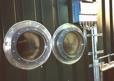 Control glasses for an industrial digester for solid organic waste, TBW, Germany Control glasses for an industrial digester for solid organic waste, TBW, Germany |
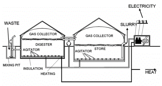
To give an overview, we have chosen three fictitious designs as they could be found in, for example, Europe. The designs are selected in a way that all the typical elements of modern biogas technology appear at least once. All designs are above-ground, which is common in Europe. Underground structures, however, do exist.
Mixing pit varies in size and shape according to the nature of substrate. It is equipped with propellers for mixing and/or chopping the substrate and often with a pump to transport the substrate into the digester. At times, the substrate is also pre-heated in the mixing pit in order to avoid a temperature shock inside the digester.
Fermenter or digester is insulated and made of concrete or steel. To optimize the flow of substrate, large digesters have a longish channel form. Large digesters are almost always agitated by slow rotating paddles or rotors or by injected biogas. Co-fermenters have two or more separated fermenters. The gas can be collected inside the digester, then usually with a flexible cover. The digester can also be filled completely and the gas stored in a separate gas-holder.
Gas-holder is usually of flexible material, therefore to be protected against weather. It can be placed either directly above the substrate, then it acts like a balloon plant, or in a separate 'gas-bag'.
slurry store for storage of slurry during winter. The store can be open (like conventional open liquid manure storage) or closed and connected to the gas-holder to capture remaining gas production. Normally, the store is not heated and only agitated before the slurry is spread on the field.
Gas use element is in Europe in 95% of the cases a thermo-power unit which produces electricity for the farm, the grid and heat for the house, greenhouses and other uses. The thermo-power unit has the advantage, that the required energy can be produced in any mixture of gas and fossil energy. It can, therefore, react to periods of low gas production and high energy requirements or vice versa.
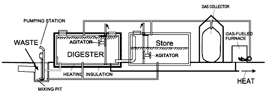 Concrete digester with two chambers (one heated, one unheated for storage) Concrete digester with two chambers (one heated, one unheated for storage)Source: TBW |
 Concrete digester with integrated plastic gas-holder Concrete digester with integrated plastic gas-holderPhoto: TBW |
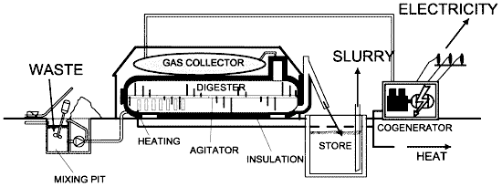 Steelvessel fermenter with seperate ballon gas-holder Steelvessel fermenter with seperate ballon gas-holderPhoto: TBW |
Selection of appropriate design
In developing countries, the design selection is determined largely be the prevailing design in the region, which, in turn takes the climatic, economic and substrate specific conditions into consideration. Large plants are designed on a case-to-case basis.
Typical design criteria are:
Space: determines mainly the decision if the fermenter is above-ground or underground, if it is to be constructed as an upright cylinder or as a horizontal plant.
Existing structures may be used like a liquid manure tank, an empty hall or a steel container. To reduce costs, the planner may need to adjust the design to theses existing structures.
Minimizing costs can be an important design parameter, especially when the monetary benefits are expected to be low. In this case a flexible cover of the digester is usually the cheapest solution. Minimizing costs is often opposed to maximizing gas yield.
Available substrate determines not only the size and shape of mixing pit but the digester volume (retention time!), the heating and agitation devices. Agitation through gas injection is only feasible with homogenous substrate and a dry matter content below 5%. Mechanical agitation becomes problematic above 10% dry matter.
Ballon plants
A balloon plant consists of a heat-sealed plastic or rubber bag (balloon), combining digester and gas-holder. The gas is stored in the upper part of the balloon. The inlet and outlet are attached directly to the skin of the balloon. Gas pressure can be increased by placing weights on the balloon. If the gas pressure exceeds a limit that the balloon can withstand, it may damage the skin. Therefore, safety valves are required. If higher gas pressures are needed, a gas pump is required. Since the material has to be weather- and UV resistant, specially stabilized, reinforced plastic or synthetic caoutchouc is given preference. Other materials which have been used successfully include RMP (red mud plastic), Trevira and butyl. The useful life-span does usually not exceed 2-5 years.
Advantages: Standardized prefabrication at low cost; shallow installation suitable for use in areas with a high groundwater table; high digester temperatures in warm climates; uncomplicated cleaning, emptying and maintenance; difficult substrates like water hyacinths can be used. </div> Disadvantages: Low gas pressure may require gas pumps; scum cannot be removed during operation; the plastic balloon has a relatively short useful life-span and is susceptible to mechanical damage and usually not available locally. In addition, local craftsmen are rarely in a position to repair a damaged balloon. </div> Balloon biogas plants are recommended, if local repair is or can be made possible and the cost advantage is substantial.
Horizontal plants
Horizontal biogas plants are usually chosen when shallow installation is called for (groundwater, rock). They are made of masonry or concrete.
Advantages: Shallow construction despite large slurry space.
Disadvantages: Problems with gas-space leakage, difficult elimination of scum.
Earth-pit plants
Masonry digesters are not necessary in stable soil (e.g. laterite). It is sufficient to line the pit with a thin layer of cement (wire-mesh fixed to the pit wall and plastered) in order to prevent seepage. The edge of the pit is reinforced with a ring of masonry that also serves as anchorage for the gas-holder. The gas-holder can be made of metal or plastic sheeting. If plastic sheeting is used, it must be attached to a quadratic wooden frame that extends down into the slurry and is anchored in place to counter its buoyancy. The requisite gas pressure is achieved by placing weights on the gas-holder. An overflow point in the peripheral wall serves as the slurry outlet.
Advantages: Low cost of installation (as little as 20% of a floating-drum plant); high potential for self help approaches.
Disadvantages: Short useful life; serviceable only in suitable, impermeable types of soil.
Earth-pit plants can only be recommended for installation in impermeable soil located above the groundwater table. Their construction is particularly inexpensive in connection with plastic sheet gas-holders.
Ferrocement plants
The ferro-cement type of construction can be applied either as a self-supporting shell or an earth-pit lining. The vessel is usually cylindrical. Very small plants (Volume under 6 m3) can be prefabricated. As in the case of a fixed-dome plant, the ferrocement gasholder requires special sealing measures (proven reliability with cemented-on aluminium foil).
Advantages: Low cost of construction, especially in comparison with potentially high cost of masonry for alternative plants; mass production possible; low material input.
Disadvantages: Substantial consumption of essentially good-quality cement; workmanship must meet high quality standards; uses substantial amounts of expensive wire mesh; construction technique not yet adequately time-tested; special sealing measures for the gas-holder are necessary.
Ferro-cement biogas plants are only recommended in cases where special ferro-cement know-how is available.
back to "Biogas" section

