Internal Wind Park Cabling
Overview
Many wind turbines generate electricity at a voltage of 690V, which is classified as low in terms of common electricity transfer systems. Large modern turbines increasingly use higher voltage levels like 10-12 kV. If power is produced at a low voltage level, the output is often stepped up by a tranformer installed directly at the wind turbine before it is fed into the internal grid between the turbines of a wind park[1]. This internal grid provides transfer of the generated energy to the grid connection point. Cables and cabling concepts have to be chosen appropriately for the expected power to be transfered.
Cabling Concept[2]
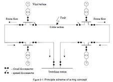
There are two common base alternatives for an internal cabling concept: radial feeders and ring feeders.The ring feeder concept is the most reliable concept, based on the n-1criterium. N-1 criteria ensure that the disconnection of any equipment of the network is allowed without serious consequences for the total network. This is valid for the grid devices like cables, transformers, substations, busbars, etc. In the case of a cable section fault, the corresponding cable section will be disconnected automatically, and all wind turbines will still keep in power production, supplying in both directions through the operative cable sections, as shown schematically in the following figure.
However, the ring concept is more expensive than the radial concept because the double cable length (preferably even in a separate trenches), the additional two disconnectors for each cable section, as well as an additional switching station feeder for each ring in order to ensure the ring concept.
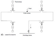
The radial feeder concept is more economical than ring feeder. There is only one way cable necessary for each area. In case of a wind turbine or transformer fault, the corresponding device will be disconnected and the remaining wind turbines stay connected to a feeder and still produce power. The main disadvantage of this concept is the low reliability in case of a cable section fault (short circuit). The whole feeder will be disconnected for a time period for the repairing works.
The principle scheme of the radial concept is shown in the following figure:
It is advantageous to implement the internal cabling with several radial feeders in order to increase the generation availability (in case of above described cable section fault only one feeder will be disconnected and remaining one will still supply the power to grid).
Cable Type
The selection of the optimal cable type and its cross section depends on both the arrangement and grouping of wind turbines (number and power of turbines) and also the choice of feeder concept.
Important parameters for the choice of the cable type are:
- the expected load factor,
- the operating temperature
- climatic and operational factors
It has to be determined, which amount of installed power the cables should transfer. This value as well as economic considerations influence the choice of the cross section used for cables. It is often economical more beneficial to use cable of a smaller cross sections for the with lower power transfer and cables with larger cross sections for the feeder connection.
To calculate the power flows the exact cabling layout has to be known: In a wind park normally wind turbines are bundled into groups of several MW. Using the a radial feeder concept this strategy is favourable, because failures in the internal grid only influence the one group of the wind park. The second reason for coupling wind turbines into groups is keeping the necessary diameter of internal cables smaller.
Earthing Network
The wind turbines of a wind park have to be effectively protected against lightnings. Technically this is done by an earthing system installed at the wind park site. The earthing network is composed by the wind turbines earthing system, and the wind farm earthing connection. In order to have a system at the same electrical potential, each wind turbine is connected to, at least, one other wind turbine.
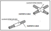
The earthing network of the wind farm is composed of copper cables of 95 mm² to be installed directly on the trench.
Earthing rods shall be solid, copper-clad steel rods with a minimum diameter of 16 mm with provision for coupling together with a suitable clamp for connection of the ground wire. The copper coating shall have a minimum thickness of 0.3 mm. The earthing rod arrangement shall have the principle layout.
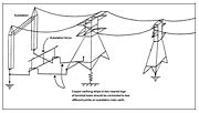
The ground wire shall be directly connected to the pole with bolted connectors, of an approved material, suitable for use with the ground wire such that galvanic action, i.e. chemical reaction between copper and galvanised steel, is minimised.
Connections to the substations earthing grid shall be made by compressed clamps or bolted connectors of approved design. The earthing of the wind park shall be connected to the existing ground network in the substation.
The terminal tower should always be connected to the substation earthmat. The reason for bonding the terminal tower to the substation earthmat is to obtain a very low impedance at the terminal tower in order to prevent a back-flash at the terminal tower in the event of lightning striking the terminal tower.
If the terminal tower cannot be bonded to the substation earthmat, the tower footing resistance of the thermal tower on its own should then be reduced to less than 10 ohm in order to still prevent back-flash at the terminal tower, in the event of lightning striking the terminal tower.
►Go to Top
Switching Station
Within a proposed internal cabling concept, there is a certain number of incoming radial feeders to the switching station busbars. An higher capacity transmission line normally connects to the transformer 15 kV /132 kV / 230 kV, depending on the voltage-level of the power grid the electricity is fed in.
It is advantageous to locate the 33 kV switching Station in the central area of the Wind Park. The length of cable and overhead transmission line can be reduced with the proposed implementation and problems regarding electrical parameters such as voltage drop, higher power losses, cable costs etc. can be avoided. The size of the chosen power transformer depends on the installed power of the wind project.
Further Information
References
- ↑ European Wind Energy Association (2004) Wind Energy - the Facts Volume 1 - Technology, retrieved 19.7.2011 [[1]]
- ↑ he contents of this article have been prepared by the project team of the feasibility study of the Ethiopian wind park Mesobo-Harena, conducted by the Deutsche Gesellschaft für internationale Zusammenarbeit (GIZ) in cooperation with the Austrian development agency and Lahmeyer international. Originally the contents have been published as: GTZ (2006) Feasibility Study for Wind Park Development in Ethiopia and Capacity Building - Mesobo-Harena Wind Park Site), retrieved 19.7.2011 [[2]]

